Volta-Type Condensing Electroscope (ca. 1930s)
This is a gold leaf electroscope that was manufactured by Griffin & Tatlock Ltd. of London, England. Based on its general appearance, and the fact that the company name was first used in 1929, I would guess that it dates from the 1930s.
Like any gold-leaf electroscope, it was intended for qualitative demonstrations of various electrostatic phenomena.
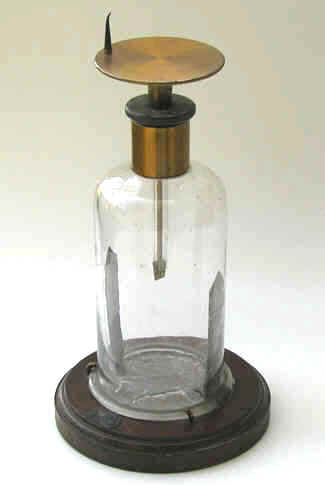
The body is glass. The wooden base is mahogany. The circular Volta plate and the vertical rod (the lead-in) from which the gold leaves would be suspended, are brass. No insulator is necessary since the glass body is non-conductive.
Alas, the two gold leaves are missing.
The bottom of the glass jar is in contact with a tin foil disk attached to the wooden base. During use, this foil disk might or might not be grounded.
Also attached to the foil are two "earthing strips" that run half way up the glass wall of the jar.
Earthing strips (aka screening strips) like these, or brass rods like those in the Ducretet Gold Leaf electroscope, are commonly found in electroscopes that have a non-conductive glass body. They seemed to have had two functions. First, they shielded (screened) the leaves from static charges on the glass or nearby charged objects. For this to work, the foil disk to which the strips were connected had to be grounded.
Quoting Samuel S. Richardson:
"It is often necessary to shield delicate instruments from the disturbing effect of neighboring charged bodied. This may be done by placing them inside a metal hollow conductor. If a gold-leaf electroscope is placed inside a can it will be shielded from the influence of a charged rod outside. An electroscope with glass walls is screened by tinfoil strips or wire gauze attached to the inner surface of the glass. An electrometer is provided with a brass case, or "bird-cage," which serves the same purpose."
The other function attributed to these strips was that they make the electroscope more sensitive.
Quoting Arthur L. Kimball:
"There are induced charges on the metal strips inside the electroscope. These charges are opposite to the charge on the [gold] leaves and increase their divergence."
The needle-like object attached to the top of the disk creates a corona discharge point. Its purpose was to demonstrate the phenomenon of a corona discharge (i.e., the leakage of charge from a point). It has a threaded end and can be affixed to the plate so that it is either pointing up or down.
Condensing Electroscopes and the Electrophorus
Condensing Electroscopes
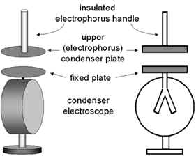
The defining feature of the condensing electroscope is the flat horizontal disk on top that is connected to the electroscope leaves (or leaf). This type of electroscope is primarily intended for electrostatic measurements but it can also be used to help identify the presence of radioactive material.
A condensing electroscope is designed to be charged with the disk of a device known as an electrophorus. The dimensions of this disk are the same as those of the fixed disk on top of the electroscope. The handle of the electrophorus disk is a glass (or other insulating material) rod projecting at right angles from the back side of the disk.
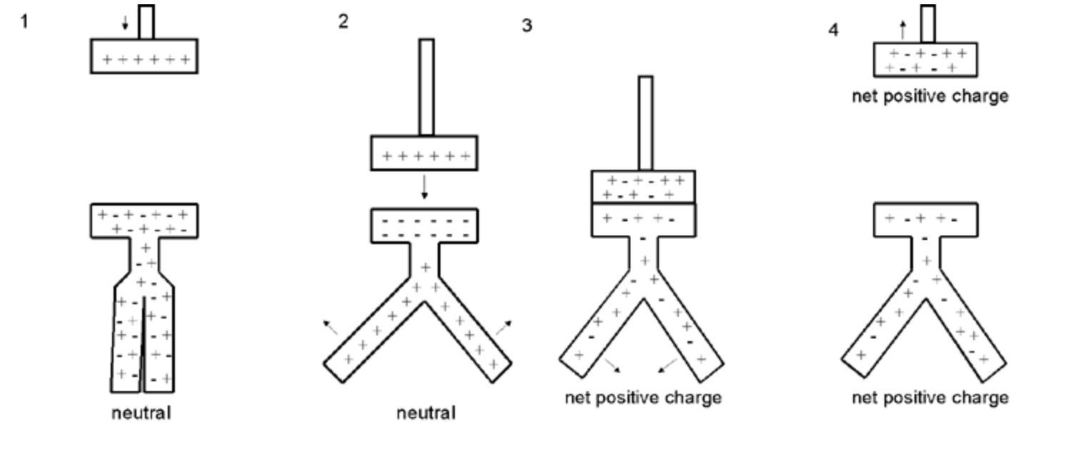
Charging the Electrophorus Disk
To begin, a charge must be generated on an insulating plate once known as the cake—this plate is considered part of the electrophorus. The charged plate (Figure 1) should have a smooth surface and be made from an insulating material (Teflon is perfect but plexiglass is a good choice). The plate is charged via friction by rubbing it with a material such as wool, silk or fur. Depending on the materials used, the resulting charge on the plate would be either negative (as shown here) or positive. The back (down) side of the insulating plate might, or might not, be in contact with a conductor that is grounded.
Next, the neutral electrophorus disk is brought in contact with the insulating plate. For the purpose of this discussion, the plate is assumed to have a negative charge. Although they are in contact, the plate does not transfer a charge to the disk because the plate is an insulator. Nevertheless, there is a spatial separation of the positive and negative charges in the disk: the negative charges (electrons) are repelled to the up side of the disk farthest away from the plate thus leaving a positive charge on the down side of the disk that is in contact with the charged plate (Figure 2).
Next, the disk is grounded, e.g., by touching the top of the disk with a finger. This causes the electrons to travel to ground leaving the disk with a net positive charge (Figure 3). Finally, the ground is removed and the electrophorus disk lifted away from the insulating plate (Figure 4).
Charging the Electroscope with the Electrophorus Disk by Conduction
There are two methods that can be used to charge the electroscope: by conduction and by induction.
To charge the electroscope by conduction, the electrophorus disk, which in this example has a positive charge, is brought into physical contact with the fixed disk on the electroscope Figure 3 below). Since electrons from the electroscope are drawn to electrophorus disk, the electroscope disk and leaf will be left with a net positive charge, the same charge as that on the electrophorus.
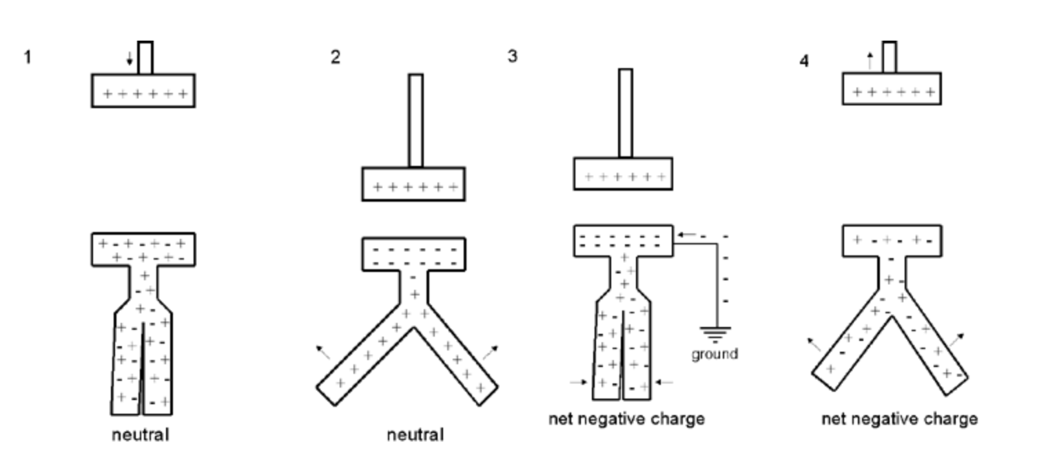
Charging the Electroscope with the Electrophorus Disk by Induction
More control of the charge transferred to the electroscope can be obtained by charging it by induction in the following manner. The charged electrophorus disk is brought close to the fixed disk of the electroscope but the two are not allowed to touch. When the electrophorus disk is brought close, the electroscope leaves will separate. The reason is that the electrons are attracted to the upper surface of the electroscope disk, the side closest to the electrophorus, leaving the leaves with a positive charge. Since both leaves have the same charge, they separate (Figure 2). By moving the electrophorus disk away from or closer to the electroscope disk, the desired separation of the leaves can be obtained. Next the electroscope disk is grounded, e.g., by touching it. The electrons then travel to the disk leaving the electroscope with a net negative charge (Figure 3). The ground is removed (Figure 4) and the electrophorus lifted away from the electroscope leaving the electroscope with a net negative charge.
Size: ca. 10" high, 3" diameter
References
- Kimball, A.L. A College Text-book of Physics. 1911.
- Richardson, S. S. Magnetism and Electricity and the Principles of Electrical Measurement. 1908.