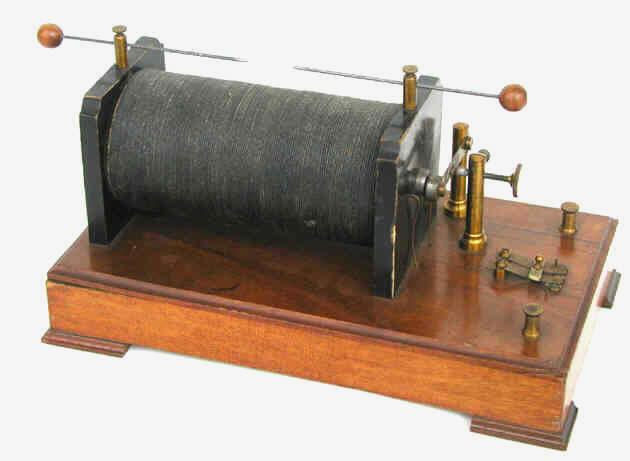
Induction Coil (ca. 1900)
Until 1920 or so, the high voltages (tens of thousands of volts) required for X-ray work were generated with either induction coils, high frequency Tesla coils, or static machines. Although each had its advantages, induction coils were generally the preferred high voltage power source.
A direct current (DC) was usually provided to the induction coil by a battery of cells or accumulators. Alternating current could also be used, but in the early days of X-rays, the AC supply was often unreliable.
The induction coil incorporates two separate coils: a primary and a secondary. The inner "primary" coil consists of insulated wire wrapped around a central iron core. The outer "secondary" coil is wrapped around the primary.
When current is supplied to the primary coil, a voltage is induced in the secondary coil that is greater than the voltage applied to the primary—the ratio of the voltages is the same as the ratio of the number of turns in the two coils. For example, if the voltage provided to the primary coil is 10 volts, and the number of turns in the primary and secondary coils are 200 and 400,000 respectively (a 2000 to 1 ratio), the induced voltage in the secondary coil is 20,000 volts. At the same time that the coil increased the voltage, it also reduced the current.
Unfortunately, the actual voltage produced in the secondary was difficult to measure accurately. Instead, it was estimated from the maximum distance a spark could jump across a spark gap connected to the terminals of the secondary coil. In fact, coils were rated by the length of their spark (e.g., 4,” 8," 12," etc.). Multiplying the spark gap (in inches) by 10,000 and adding 10,000 provided a rough approximation of the voltage. How “fat” the spark was gave a crude idea as to the current (milliamperes).
The catch is that a steady current in the primary coil does not induce a current in the secondary. For current to be generated in the secondary, there must be a change in the magnetic field created by the primary coil. More precisely, the magnetic field must undergo repeated and rapid changes. This is accomplished by rapidly turning the current through the primary coil on and off. The device that does this is known as an interrupter because it interrupts the current.
The simplest type of interrupter, like the one on our induction coil, was mechanical. While it might have been acceptable for light work, a mechanical interrupter would experience problems (e.g., arcing inverse discharges) when used with large currents. And, it was noisy. For serious work, a mercury interrupter or an electrolytic interrupter was required.
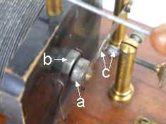
The mechanical interrupter on our coil works in the following manner.
When current is applied to the primary coil, the iron hammer (a) on the end of the contact arm is pulled to the magnetized iron contact (b) at the end of the primary's iron core. This breaks the interrupter's contacts (c) which stops the flow of current to the primary. Since the core is no longer magnetized, the contact arm then returns to its normal resting position. When this happens, the interrupter's contacts are closed again and current flows to the primary. The result is a rapid turning on and off of the current to the primary. It is the repetitive establishment and collapse of the primary's magnetic field that induces the high voltage in the secondary coil.
By 1920, a significant number of radiologists had switched to transformers. These devices stepped up the voltage supplied by alternating line current (AC) which had become widely available and relatively reliable. And by the end of the 1920s, transformers were pretty much the only source of high voltage being employed, at least in fixed installations where AC was available. Transformers were simpler, quieter and more reliable than induction coils.
There was also a type of hybrid transformer introduced in 1907 by Homer Snook worth mentioning: the interrupterless transformer. It used a DC (or AC) powered motor to generate an alternating current. This current was supplied to a transformer that increased the voltage. Since the stepped up current was still AC, it had to be rectified. When it worked, it was impressive—capable of producing 100 kVp at 100 mA. The one problem was the unreliability of the valve tube used to rectify the current.
The example shown here is too small to have been useful for X-ray work. Instead, it would have been intended for use in schools, i.e., classroom demonstrations. The manufacturer and date of production are unknown.
Size: The base is 7" x 12" while the coil is 3" in diameter and 6.5" long.