Gundelach "Moment" X-Ray Tube (1912-1920)
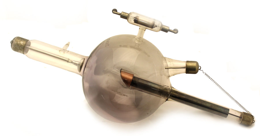
Known as the "Moment Rohre," the large bi-anode beauty shown here was manufactured by the Gundelach company, most likely between 1912 and 1920. This particular version of the Moment Rohre employed a tungsten target whereas that found in the first version of the tube (introduced in 1910) was platinum.
Presumably the name refers to the fact that the tube’s output was sufficiently intense to create a useful diagnostic image in a “moment.” The shorter the exposure, the sharper the image would be.
It was intended for use with a rectified alternating current (Ronne and Nielsen, 1986)
In the top photo, the heavy copper block that served as a heat sink for the tungsten target is seen in the center of the bulb. The cup-shaped aluminum cathode can be seen near the point where its enclosing glass arm is attached to the left side (as seen in the photo) of the bulb. The anode is the aluminum rod inside the short glass arm “entering” the tube from the right side.
The black metal tube extending from the back of the target almost to the end of the glass arm (down to the right in the photo) helped cool the target by radiating heat through the glass.
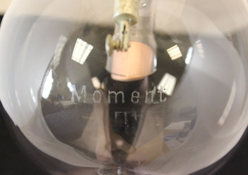
As you can see in the image to the right, a "T" is etched on the bulb below "Moment." I am not sure what it stands for. "Tungsten" would be a good guess if it weren't for the fact that the German word for tungsten is Wolfram. Gundelach did use "T" to designate their therapy tubes (e.g., the "therapy-constant" TK tube), however the moment tube was intended for imaging rather than therapy.
Although the actual color of the glass is not as dark as it appears in the photo, it is dark enough to indicate that the tube was well used.
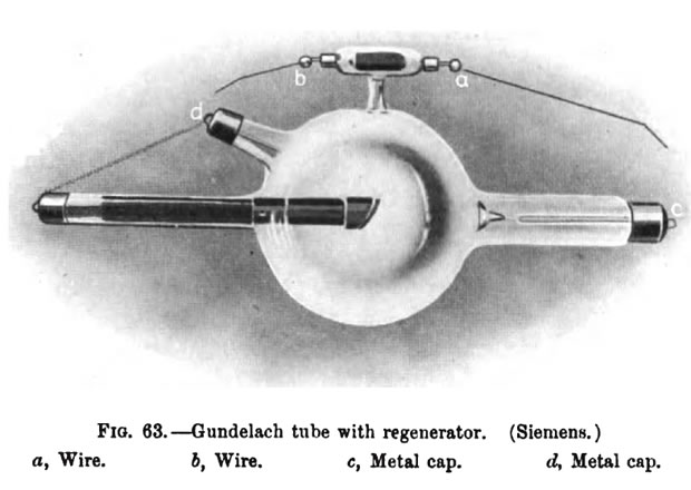
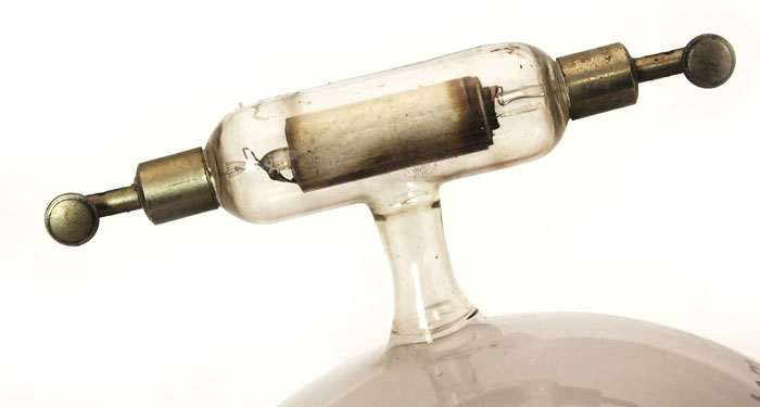
There is a fitting at each end of the regulator (see above) for a wire lever that would be used to create a spark gap (or direct contact) with the terminals for the anode and cathode. This regulator is of such similar construction to that of the collection's air-cooled tube that I will repeat the latter's description here (Knox, 1919). The regulator, aka regenerative device:
"consists of a little condenser which is made in the form of a cylindrical glass tube covered with an imperfect conductor of electricity. By special treatment this conductor is made to absorb a large quantity of gas. It is then covered with a second glass tube." ... When the tube has become too hard, put the wire b of the regenerating arrangement in contact with metal cap d of the tube.. The other wire a has to be so far from the metal cap c that a shunt-spark passes. ... The current produces some gas from the substance of the regenerating arrangement, and after a few minutes the tube will again fluoresce regularly. The regeneration, however, is only completed when the shunt-sparks have ceased to pass. After regeneration turn back both wires."
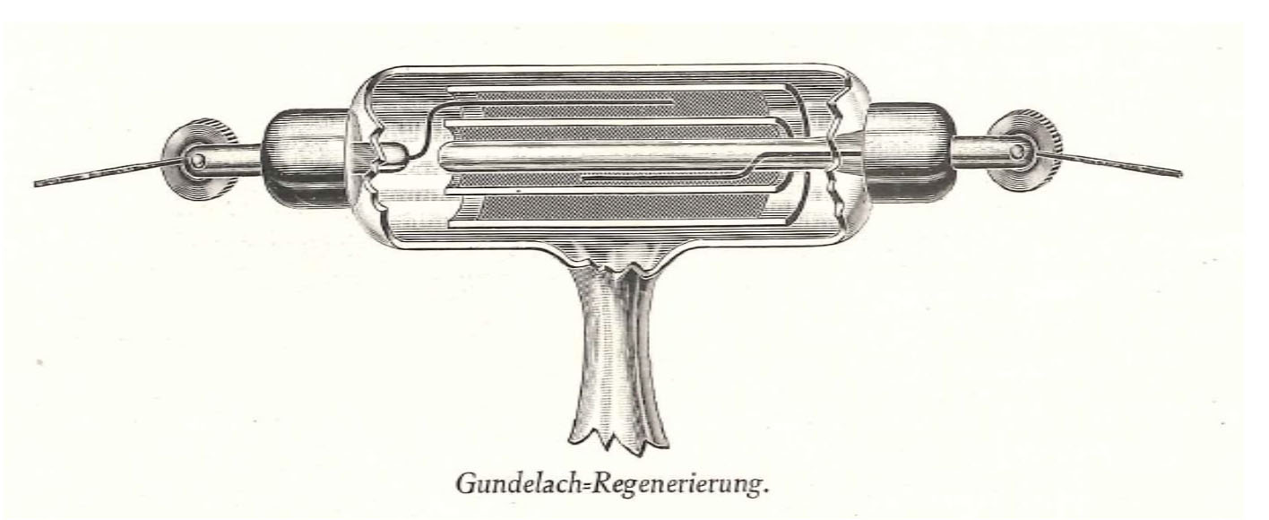
Since this regulator was developed by Gundelach, it is not surprising that it is the most common type found on their tubes. The company's catalog (ca. 1910-1915), from which the above figure was taken, includes a very detailed description of the regulator's construction and use. A partial translation of this description follows:
"Much better, however, is the goal of a regenerating device designed by Gundelach, which has the shape of a small capacitor. Here two fairly strong asbestos layers are separated by a glass cylinder. If these layers are charged (also by shunt), they are not heated very strongly, but at the same time uniformly.
The two layers contain exceedingly large quantities of occluded gases, so that the regeneration can be carried out a hundred times with great success."
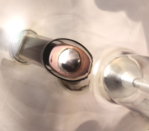
The image to the left is a nice close-up of the tube's tungsten target (anticathode). The cathode is seen to the right. What is unusual is that the tungsten is convex rather than flat. Even the surface of the copper has a slight curve to it. Since the target was convex, any reflected electrons would spread out rather than strike a single point on the glass wall of the tube.
The Siemens company developed the method by which tungsten could be formed into a target in 1910. In almost all respects, tungsten was better than platinum: it was cheaper, had a higher melting point, its thermal conductivity was greater, and it was less prone to sputtering.
Companies using these targets under a license with Siemens were supposed to acknowledge Siemens on the tube—something Gundelach seems to have forgotten in this case.
The photo above left also shows the open end of the glass jacket or mantle that surrounds the target. This mantle can be seen in the photo at the top of the page, but it is not as obvious. The jacket might have served two functions, intended or otherwise. First, the glass would prevent stray electrons from striking the side of the anticathode and producing X-rays. Any X-rays produced by electrons striking the glass itself would be of lower intensity than those produced by electrons striking the metal stem of the anticathode. We want the anticathode to emit X-rays, but the latter should come from the face of the target, not the stem. Second, the purpose of the glass mantle might have been related to the following phenomenon observed by Hittorf: the surface of glass located near an electrode will accumulate a static charge. The result is that this charge minimizes the emission of electrons from the electrode (in this case, what should be the target of electrons, not the source). The emission of electrons from the target would be a potential problem during periods of reversed current. See the introduction for more information concerning the problem of reversed currents.
The company logo, a scale hanging from the inside of a large "G," is etched on the stem of the tube as well as 86587 [the serial number], "D.R.P. No. 109449" [the patent number] and "D.R.G.M. No. 346585" [a registration number].
The Gundelach company was founded in 1852 by Emil Gundelach, a glass blower. Initially they offered a variety of Crookes and Geissler tubes. As a result, they were in excellent shape when the time came to begin manufacturing tubes specialized for X-ray production. In fact, they began doing so within a few month's of Rontgen's discovery. They continued producing X-ray tubes until the late 1920s.
Size: Approximately 23" long with 7" bulb diameter
References
- Knox, R. Radiography and Radiotherapeutics. Part I. 1919.
- Ronne, P. and Nielsen, A.B.W. Development of the Ion X-ray Tube. 1986.
- Grigg, E. R. N. The Trail of the Invisible Light. Charles C Thomas. 1965.
