The Snook Hydrogen Tube (1915-1925)
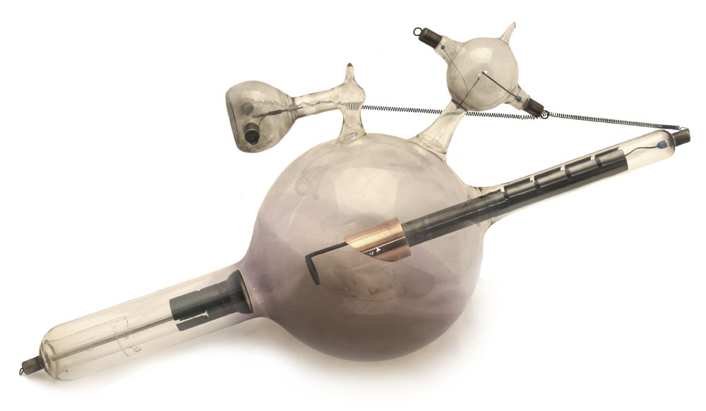
The “Snook” X-ray tube shown here is a diagnostic x-ray tube that had a unique approach to raising and lowering the internal gas pressure. But more about the latter later.
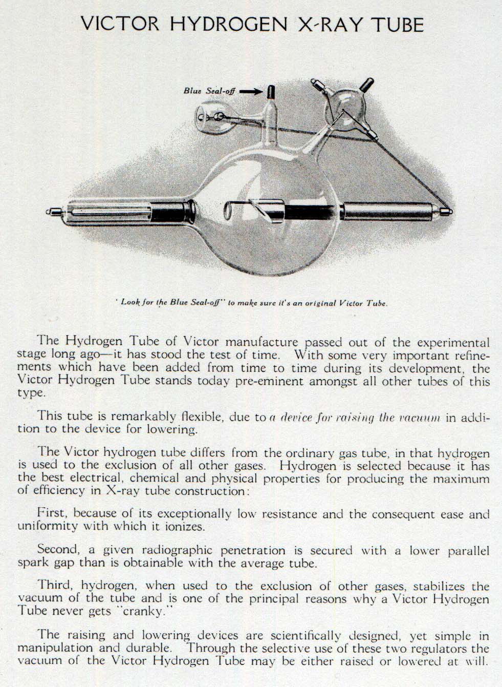
While it has no identifying markings, the tube was almost certainly manufactured by the Victor company of Chicago, sometime between 1915 and 1925. Homer Snook, who designed it, was an employee of the Victor company. In fact, at one time he was vice-president of the company.
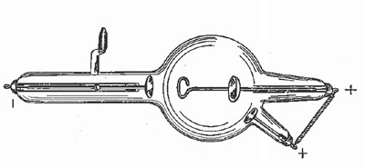
The tube only employs two electrodes, a cathode and an anode—there is no separate anticathode. In the above photo, the aluminum cathode is located at the point where the glass arm surrounding it joins the lower left side of the spherical glass bulb. The anode enters the tube from the upper right. At the free end of the anode, in the center of the bulb, is the copper-jacketed target. The target, embedded in the sloped face of the copper, is probably tungsten.
The description of the Snook tube from the Victor catalog (at bottom of page) refers to the short black metal sheath behind the cathode as the "Victor supporting protective shield." Its stated purpose was to "steady the focus and render the tube practical for use with heavy currents." Under heavy use, the positive gas ions striking the cathode might cause it to overheat. The shield would remove some of the heat from the cathode, distribute it along and dissipate it through the glass arm. Perhaps more importantly, it functioned as a heat shield preventing that portion of the glass arm closest to the outer edge of the cathode from overheating.
Similarly, the black metal tube extending behind the target was intended to dissipate heat. Note that the two metal tubes do not extend all the way to the tips of the glass arms. This was probably done to avoid heating the glass seals at the electrical terminals and compromising their integrity.
At this point it is worth mentioning that the residual gas inside the Snook tube was hydrogen, not air. Although not as inert as helium, a gas Victor used in some of their other tubes, hydrogen was less likely than air to react with the tube's metal components. This helped stabilize the tube’s performance by reducing fluctuations of the gas pressure in the tube. Something else: since hydrogen has a lower mass than other gases, less sputtering occurs when positive hydrogen ions strike the cathode than would occur with other gases. Sputtering was undesirable because it led to a hardening of the tube (lowers the gas pressure).
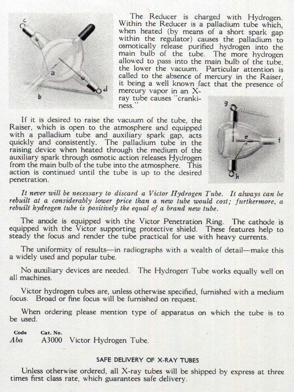
The most unique thing about the Snook tube was that it employed two separate regulators as seen in the following drawing and photo. One was called the “raiser” and the other was known as the “reducer.”
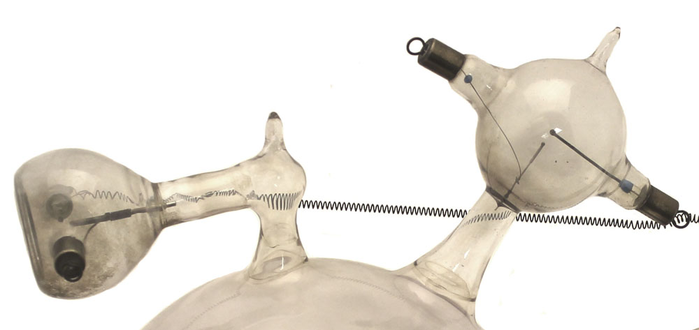
The regulator closest to the tube center (towards the left in the photo and diagram) was open to the air. When the gas pressure inside the X-ray tube got too high, current would jump from an electrode to a thin palladium tube in the regulator which then became hot. When heated, the palladium became permeable and this allowed some of the hydrogen inside the X-ray tube to escape. Because this regulator helped raise the vacuum (lower the gas pressure), it was known as the “raiser.”
The other regulator (towards the right in the photo and diagram) employed a sealed reservoir of hydrogen. When the x-ray tube became too hard, current would jump from an electrode to the thin platinum tube that connected the reservoir to the x-ray tube. The electricity heated the platinum which allowed hydrogen to diffuse from the regulator's reservoir through the platinum tube and into the X-ray tube. This increased the gas pressure (i.e., softened the tube). Since it reduced the vacuum in the tube, this regulator was known as the “reducer.”
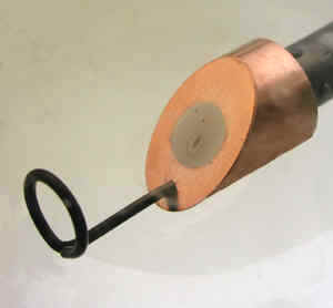
The Victor catalog stated that the “Victor Penetration Ring” (photo to the right) helped "steady the focus and render the tube practical for use with heavy currents." The same claim made for the Victor supporting protective shield attached to the cathode
This metal ring, also known as a focusing ring, is positioned midway between the target and the cathode. Such rings, not unique to Victor by the way, were said by others to ensure that the electrons from the cathode were directed to a small area (a few square millimeters) in the center of the target. The idea was that static charges on the glass of the tube could cause the focal point to wander and that the ring helped combat this phenomenon. This idea is reasonably consistent with the statement in the Victor catalog.
Tubes employing these rings were often referred to as "penetrator tubes" because the resulting X-rays were presumably more penetrating. The drawing to the left (Pusey, 1903) shows an early penetrator tube. Quoting Pusey: "It is based on the principle that with a given vacuum the penetration will be higher the closer the electrodes are together... Such tubes are preferred by some operators for fluoroscopic work in which a very high penetration is desired."
A completely different explanation has been provided by Ronne and Nielsen (1986): “the annular anode probably protects the tube against reverse current. In the ‘wrong half cycle’... it cuts off the field from the anticathode, by which atomization [sputtering] of the target is avoided, and the ring itself will not send electrons to the ‘cathode’ as the distance between then is shorter than the width of the dark space.”
All of this suggests one of two things: either these rings were helpful in many different ways, or nobody really knew what was going on.
As seen below, the Victor catalog description of their Snook tube refers to the black metal sheath behind the cathode (lower left in top photo) as the "Victor supporting, protective shield." Its purpose was to "steady the focus and render the tube practical for use with heavy currents." Under heavy use, the positive gas ions striking the cathode might cause it to overheat. As such, the shield seems to have functioned by removing heat from the cathode and dissipating it through the glass arm which would normally be relatively cool. Similarly, the black metal tube extending behind the target into its enclosing glass arm was intended to dissipate heat. Note that these tubes do not extend all the way to the tips of the glass arms. This was likely done to avoid heating the glass seals at the electrical terminals, something that might compromise their integrity.
Size: Approximately 20" long with 6.5" bulb diameter
The following images were kindly provided by Alastair Wright.
Snook also pioneered the use of transformers, which operated off alternating current, to provide the high voltage for X-ray tubes. At the time, most tubes were powered by induction coils which utilized direct current and required the use of interrupters.
References
- GWC Kaye. X-Rays. Longmans, Gree and Co. London. 1929.
- Pusey, W.A. and Caldwell, E.W. The Practical Application of the Rontgen Rays in Therapeutics and Diagnosis. 1903.
- Raper, H.R. Elementary and Dental Radiography. 1922.
- Ronne, P., Nielsen, A.B.W. Development of the Ion X-ray Tube. 1986.