Kolbe's Electrometer/Electroscope by Max Kohl (ca. 1900)
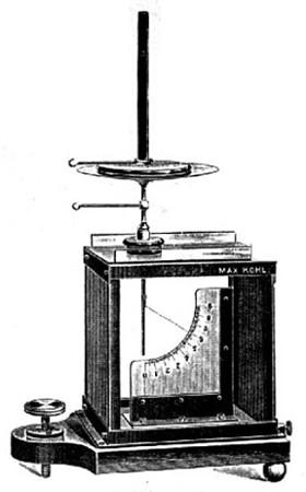
What we have here is a box-like electroscope that was designed for classroom demonstrations of electrostatic phenomena. Like any electroscope, it could be used for the measurement of radioactive materials. The curved scale (mica) numbered 0 through 9 provides at least a limited capability for quantitative comparisons. If required, the scale could be calibrated in volts. Although the Kolbe electroscope was primarily used in a classroom or laboratory, it was rugged enough to be taken into the field.
This type of instrument was first described by Bruno Kolbe of St. Petersburg in 1889. Since Kolbe referred to it as an electrometer, that is what it is generally called. In reality (i.e., in my opinion), it is an electroscope.
Is it an Electroscope or Electrometer?
Terminology
There are two methods used to distinguish electroscopes and electrometers. In neither case is the distinction perfectly clear or completely satisfactory.
The first approach employs the term electroscope for any device used to make a qualitative measurement of an electrostatic charge and to use the term electrometer for a device used to make quantitative measurements. If a scale is used, the device would therefore be considered an electrometer.
The second method, employed here, is to use the term electroscope for a device that only requires an initial charge to function. The change in this initial charge is measured by observing he movement of a leaf or fiber. No auxiliary potential is necessary. An electrometer, on the other hand, requires the maintenance of a fixed auxiliary potential (e.g., between two pairs of quadrants). The change in the collected charge being measured causes the movement of a vane, needle or fiber within the electric field created by the auxiliary potential.
Some of the instruments in the collection that have been described as electrometers could just as easily, and perhaps more appropriately, have been described as electroscopes.
Advantages of Electrometers
- Electrometers are usually more sensitive than electroscopes.
- It is fairly easy to change the sensitivity of an electrometer.
Advantages of Electroscopes
- Electroscopes are unaffected by changes in temperature and humidity.
- They do not require a stable source of power.
- They are simple to set up and use.
- They are portable and relatively resistant to vibration.
- They are relatively inexpensive.
In general, electroscopes were preferred by chemists while physicists preferred to use electrometers. Nevertheless, despite the greater sophistication of the electrometer, the electroscope was often the instrument of choice.
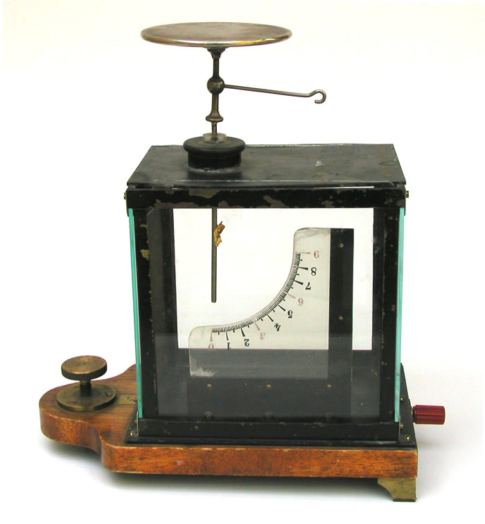
A Kolbe electroscope employs a single leaf—the mangled fragment of a leaf can be seen attached to the vertical support rod in the above photo. The leaf was usually aluminum, but ours (or what is left of it) is gold. Paper leaves were also used. The metal components of the case were painted black in order to eliminate bothersome reflections of light. The four vertical sides of the case are glass while the top and bottom are sheet metal. The two glass sides that are not in view are covered on the inside with a metal screen to prevent static charges on the glass or nearby objects from affecting the movement of the leaf. The brass knob on the left end of the wooden base is used to level the electroscope and the red connector on the right end is used to ground the case. The insulator that separates the vertical support rod from the metal top of the case appears to be quartz.
The maker's name is printed on the top of the case: Max Kohl A.G. Chemnitz.
Kolbe electroscopes either had a hollow metal ball, or a horizontal disk, at the top of the vertical supporting rod. To minimize the loss of any stored electrical charge, these things had smooth rounded surfaces. Obviously, our electroscope has a disk. Such a disk was usually referred to as a condenser (or Volta plate) because it stored the charge applied to the electroscope. In general, a device called an electrophorus would be used to charge the condenser.
Condensing Electroscopes and the Electrophorus
Condensing Electroscopes
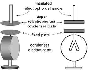
The defining feature of the condensing electroscope is the flat horizontal disk on top that is connected to the electroscope leaves (or leaf). This type of electroscope is primarily intended for electrostatic measurements but it can also be used to help identify the presence of radioactive material.
A condensing electroscope is designed to be charged with the disk of a device known as an electrophorus. The dimensions of this disk are the same as those of the fixed disk on top of the electroscope. The handle of the electrophorus disk is a glass (or other insulating material) rod projecting at right angles from the back side of the disk.
Charging the Electrophorus Disk
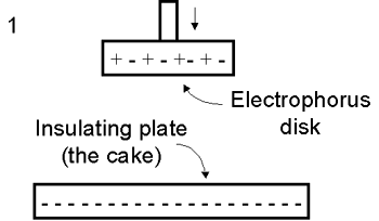
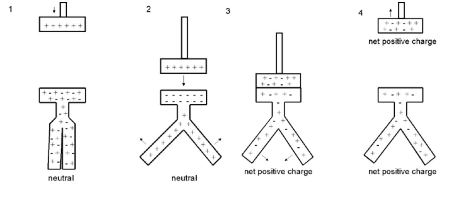
To begin, a charge must be generated on an insulating plate once known as the cake—this plate is considered part of the electrophorus. The charged plate (Figure 1) should have a smooth surface and be made from an insulating material (Teflon is perfect but plexiglass is a good choice). The plate is charged via friction by rubbing it with a material such as wool, silk or fur. Depending on the materials used, the resulting charge on the plate would be either negative (as shown here) or positive. The back (down) side of the insulating plate might, or might not, be in contact with a conductor that is grounded.
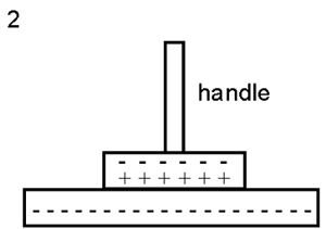
Next, the neutral electrophorus disk is brought in contact with the insulating plate. For the purpose of this discussion, the plate is assumed to have a negative charge. Although they are in contact, the plate does not transfer a charge to the disk because the plate is an insulator. Nevertheless, there is a spatial separation of the positive and negative charges in the disk: the negative charges (electrons) are repelled to the up side of the disk farthest away from the plate thus leaving a positive charge on the down side of the disk that is in contact with the charged plate (Figure 2).
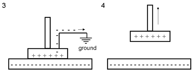
Next, the disk is grounded, e.g., by touching the top of the disk with a finger. This causes the electrons to travel to ground leaving the disk with a net positive charge (Figure 3). Finally, the ground is removed and the electrophorus disk lifted away from the insulating plate (Figure 4).
Charging the Electroscope with the Electrophorus Disk by Conduction
There are two methods that can be used to charge the electroscope: by conduction and by induction.
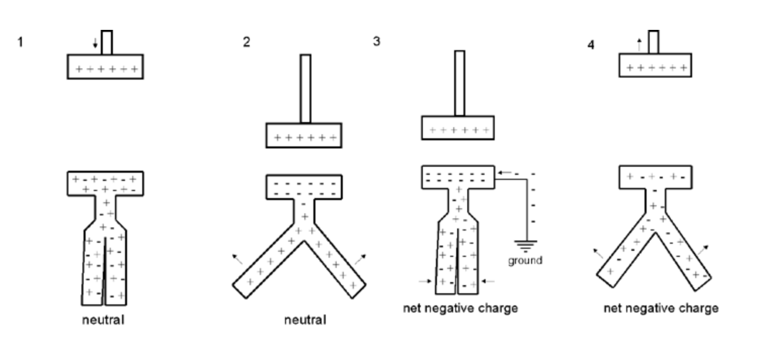
To charge the electroscope by conduction, the electrophorus disk, which in this example has a positive charge, is brought into physical contact with the fixed disk on the electroscope Figure 3 below). Since electrons from the electroscope are drawn to electrophorus disk, the electroscope disk and leaf will be left with a net positive charge, the same charge as that on the electrophorus.
Charging the Electroscope with the Electrophorus Disk by Induction
More control of the charge transferred to the electroscope can be obtained by charging it by induction in the following manner. The charged electrophorus disk is brought close to the fixed disk of the electroscope but the two are not allowed to touch. When the electrophorus disk is brought close, the electroscope leaves will separate. The reason is that the electrons are attracted to the upper surface of the electroscope disk, the side closest to the electrophorus, leaving the leaves with a positive charge. Since both leaves have the same charge, they separate (Figure 2). By moving the electrophorus disk away from or closer to the electroscope disk, the desired separation of the leaves can be obtained. Next the electroscope disk is grounded, e.g., by touching it. The electrons then travel to the disk leaving the electroscope with a net negative charge (Figure 3). The ground is removed (Figure 4) and the electrophorus lifted away from the electroscope leaving the electroscope with a net negative charge.
For more information about the Kolbe electroscope/electrometer, refer to the description of the Leppin & Masche electroscope.
Notice that the numbers on the scale are upside down. The reason is that the electroscope was designed so that the movement of the leaf on the scale could be projected onto a large screen for better viewing. The projection would invert the image. How this might be done is shown in the figure to the right—the figure is from a 1908 text by Bruno Kolbe. The following quote is from that text:
"Of course, we must write the numbers the reverse way, so that they may appear right on the white screen."
The image to the right is from a Max Kohl catalog (ca.1910-1920) that identifies this instrument as "Aluminum Electrometer (Kolbe's)." The catalog description follows:
"with projection scale for calibrating and amber tubes in ceramic plug, one ball 10 mm diameter, two condenser plates (lacquered) with one ebonite handle, one extra ebonite plug with amber tubes, conductor rod and paper leaves. The sheet iron house of the instrument is 130 mm high, 140 mm wide, 95 mm deep." Except for what you see in the photo, everything else listed in the catalog is missing. The price was 3 pounds.
The following is the description of an identical instrument in a Baird & Tatlock catalog (1912):
"Electrometer (Kolbe's), for exact measurements, consisting of case with insulated rod and aluminum leaf. Two mica plates, one divided into degrees, are supplied with each apparatus." The price was 4 pounds.
Clearly, it was a much better deal to buy it from Max Kohl than Baird & Tatlock.
Size: ca 9.5" tall. The chamber is 5.5" high 5.5" wide and 4" deep. The condenser (Volta) plate is ca. 3" in diameter. The wooden base is 9" x 4.5."
I would like to express my thanks to Jean-François Loude for providing the above reference.
References
- Kolbe, B. An Introduction to Electricity. Translated by J. Skellon. 1908.
- Kolbe, B. Ein einfaches Elekrometer. Zeitschrift fur den Physikalischen und Chemischen Unterricht. April 1889; 153-159.
- Max Kohl A.G. Chemnitz. Physical Apparatus. Price List No. 50. Vols. II and III. No date.