Kolbe's Electrometer/Electroscope by Leppin & Masche (ca. 1900)
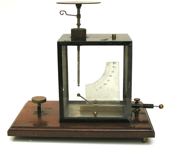
This example of a Kolbe electroscope (or electrometer, if you prefer) was marketed by Leppin & Masche of Berlin. For the most part, it would have been used for classroom demonstrations of electrostatic phenomena. These demonstrations might, or might not, have involved the use of radioactive materials.
The maker's name is stamped on the end of the wooden base: LEPPIN & MASCHE, BERLIN.SA. Leppin & Masche was a German manufacturer of scientific equipment.
The four vertical sides of the chamber are glass, while the top and bottom are sheet metal. The inside of the glass on the right and left sides (not visible in the above photo) is covered with a wire mesh. This mesh "screened" the inside of the electroscope from the effects of static charges on nearby objects and the glass. For this to work, the metal frame and the wire mesh had to be grounded. The brass connector for grounding the electroscope is located on the far-right corner of the wooden base (as seen in the top photo). The larger brass knob on the left end of the wooden base was used to level the electroscope.
Rather than employ two gold leaves, like the "classic" Bennet electroscope, the Kolbe electroscope was designed to use a single aluminum leaf. Nevertheless, a gold leaf or a paper leaf could also be used. Unfortunately, our leaf (paper) has fallen to the bottom of the case.
The curved mica scale inside the chamber was employed to measure the deflection of the leaf—it is numbered in degrees: 0 through 90.
Unlike the other Kolbe electroscope in the collection, this one has a horizontal metal rod that penetrates the chamber (from the lower right side as seen in the top photo). The brass ball at the angled end of the rod, the end inside the chamber, can be brought into contact with the ball at the bottom of the vertical supporting rod in order to ground discharge (ground) the leaf.
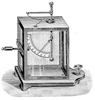
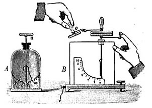
Just below the condenser plate on the top of the electroscope, you can see a "hooked" wire rod projecting towards the left. In some instruments this device, which served as an electrical terminal, had a metal ball at the end instead of a hook. It projected far enough outward that you could touch it as a way to ground the leaf without touching the Volta plate (figure below right). It also provided a convenient terminal for connecting the electroscope to other electrical equipment (figure below). When the electroscope was not in use, the wire might be connected to the small brass connection on the top of the electroscope case (figure to right).
The figure to the right is from Frick (1907). The other two figures are from a text by Kolbe (1908).
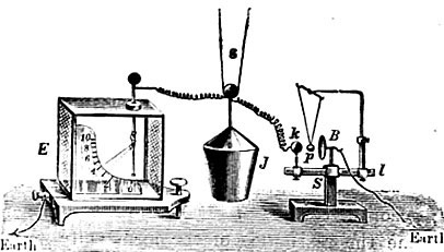
In general, an electrophorus would be used to transfer a charge to the condenser (Volta plate).
Condensing Electroscopes and the Electrophorus
Condensing Electroscopes
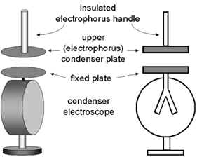
The defining feature of the condensing electroscope is the flat horizontal disk on top that is connected to the electroscope leaves (or leaf). This type of electroscope is primarily intended for electrostatic measurements but it can also be used to help identify the presence of radioactive material.
A condensing electroscope is designed to be charged with the disk of a device known as an electrophorus. The dimensions of this disk are the same as those of the fixed disk on top of the electroscope. The handle of the electrophorus disk is a glass (or other insulating material) rod projecting at right angles from the back side of the disk.
Charging the Electrophorus Disk
To begin, a charge must be generated on an insulating plate once known as the cake—this plate is considered part of the electrophorus. The charged plate (Figure 1) should have a smooth surface and be made from an insulating material (Teflon is perfect but plexiglass is a good choice). The plate is charged via friction by rubbing it with a material such as wool, silk or fur. Depending on the materials used, the resulting charge on the plate would be either negative (as shown here) or positive. The back (down) side of the insulating plate might, or might not, be in contact with a conductor that is grounded.
Next, the neutral electrophorus disk is brought in contact with the insulating plate. For the purpose of this discussion, the plate is assumed to have a negative charge. Although they are in contact, the plate does not transfer a charge to the disk because the plate is an insulator. Nevertheless, there is a spatial separation of the positive and negative charges in the disk: the negative charges (electrons) are repelled to the up side of the disk farthest away from the plate thus leaving a positive charge on the down side of the disk that is in contact with the charged plate (Figure 2).
Next, the disk is grounded, e.g., by touching the top of the disk with a finger. This causes the electrons to travel to ground leaving the disk with a net positive charge (Figure 3). Finally, the ground is removed and the electrophorus disk lifted away from the insulating plate (Figure 4).
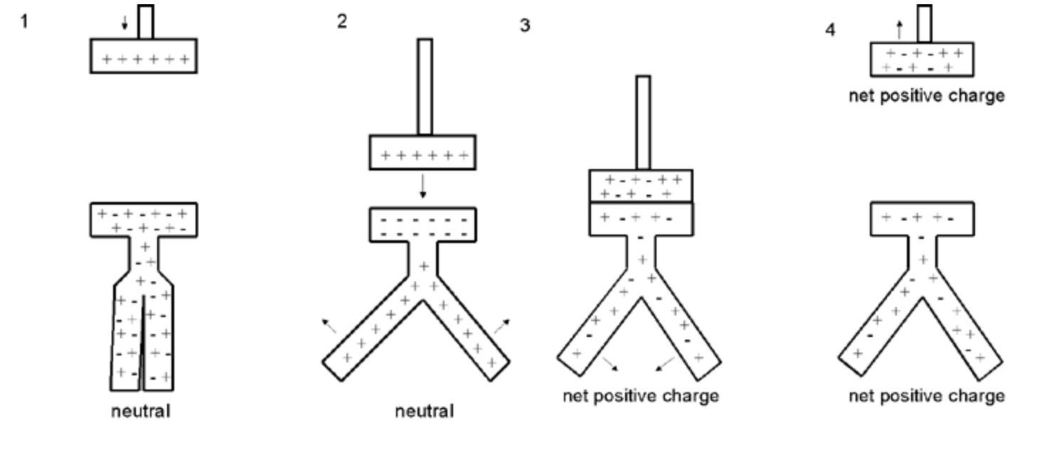
Charging the Electroscope with the Electrophorus Disk by Conduction
There are two methods that can be used to charge the electroscope: by conduction and by induction.
To charge the electroscope by conduction, the electrophorus disk, which in this example has a positive charge, is brought into physical contact with the fixed disk on the electroscope Figure 3 below). Since electrons from the electroscope are drawn to electrophorus disk, the electroscope disk and leaf will be left with a net positive charge, the same charge as that on the electrophorus.
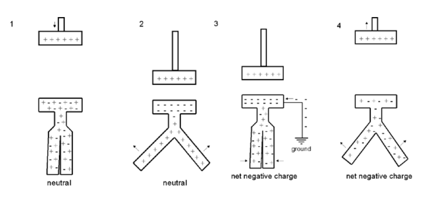
Charging the Electroscope with the Electrophorus Disk by Induction
More control of the charge transferred to the electroscope can be obtained by charging it by induction in the following manner. The charged electrophorus disk is brought close to the fixed disk of the electroscope but the two are not allowed to touch. When the electrophorus disk is brought close, the electroscope leaves will separate. The reason is that the electrons are attracted to the upper surface of the electroscope disk, the side closest to the electrophorus, leaving the leaves with a positive charge. Since both leaves have the same charge, they separate (Figure 2). By moving the electrophorus disk away from or closer to the electroscope disk, the desired separation of the leaves can be obtained. Next the electroscope disk is grounded, e.g., by touching it. The electrons then travel to the disk leaving the electroscope with a net negative charge (Figure 3). The ground is removed (Figure 4) and the electrophorus lifted away from the electroscope leaving the electroscope with a net negative charge.
For more information about the this type of electroscope, refer to the description of the of the Kolbe electroscope marketed by Max Kohl.
Size: ca 9.5" tall. The chamber is 5.5" high 5" wide and 4" deep. The condenser (Volta) plate is ca. 3" in diameter. The wooden base is 10" x 6."
I would like to express my thanks to Jean-François Loude for providing a couple of the above references.
References
- Frick, J. Physikalische Technik, oder Anleitung zu Experimentalvortragen, II. I. 1907.
- Kolbe, K. Ein einfaches Elekrometer. Zeitschrift fur den Physikalischen und Chemischen Unterricht. April 1889; 153-159.
- Kolbe, B. An Introduction to Electricity. Translated by J. Skellon. 1908.