Kesselring High Frequency Tube (1910-1920)
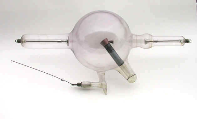
This bi-anode X-ray tube was manufactured by the Kesselring X-ray Tube Company and intended to be used with an induction (high frequency) coil as the power source.
In the photo above, the aluminum cathode can be seen at the point where its enclosing glass arm connects to the left side of the bulb. The anode, also aluminum, is located in an enlarged portion of the glass arm attached to the right side of the bulb. I suspect that this enlargement was intended to minimize the effect that a static charge on the glass might have on the operation of the anode. The same type of enlargement in the glass arm about the anode is found in two other tubes in the collection: the Bellevue Interrupterless Transformer tube and the Macalaster & Wiggin X-ray tube.
The anticathode enters the bulb from the bottom right in the photo. The circular target at the end of the anticathode (in the center of the bulb) is probably tungsten rather than platinum because many of the tube’s other design features are characteristic of tubes capable of handling high loads—employing large currents and voltages for prolonged periods would be impossible with a platinum target. One such design feature: the tube employs a “heavy anode”—the large copper heat sink that surrounds the target. Another feature of the anticathode that would help dissipate heat from the target is the black metal tube attached to the back of the copper block.
This particular anticathode has a couple of interesting features worth commenting on.
First, it is not electrically connected to the anode. In fact, the anticathode lacks any type of electrical connection. Very unusual.
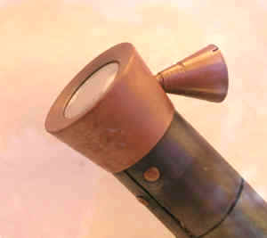
The other thing I want to comment on is the cone coming off the side of the copper block (oriented so that the cone’s open end faces the anode). One proposed explanation for the cone was that it helped shape the electric field between the cathode and anode so that the electrons from the cathode were directed towards the target. This might have been necessary because the anticathode was not connected to the anode.
However, I think the cone's primary purpose was to minimize the consequence of any periodic inverse discharges (reverse currents) whereby electrons would flow from the tube's "anode" towards its "cathode."
Inverse currents were undesirable for two reasons. First, they might cause the target to deteriorate, something that would shorten the life of the tube. Second, since the current through the tube would flow in two different directions, the X-rays would be coming from multiple points, e.g., the front and back of the target. The result: blurry radiographic images.
The following quote is from the description in the Journal of Advanced Therapeutics (1908) of "A New X-ray Tube" that was being manufactured by Machlett & Son:
"In order to destroy the inverse current when present, and add life to the tube, we have designed the tube shown [below]"... "The cathode stream [from the "anode” to the anticathode during the inverse discharge] is focused into the cone attached to the anode, where it is destroyed without doing any damage to the tube."
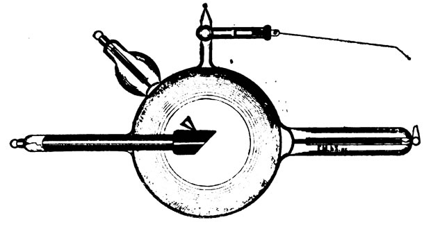
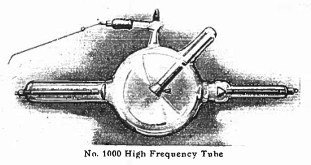
Obviously, the tube illustrated in the above drawing is a little different from our Kesselring tube. However, the following diagram from an undated Thompson & Plaster catalog is a perfect match.
Founded by Hermann M Kesselring, the Kesselring X-ray Tube Company was a small manufacturer located at 136 and/or 652 W. Lake Street and 204 N Desplaines Street in Chicago. It operated at least until 1921.
Size: Approximately 19.5" long with 6.5" bulb diameter