Kesselring Valve Tube (ca. 1900-1915)
It might have been manufactured by the Kesselring X-ray Tube Company, but it is not an x-ray tube, it is a valve tube.
The purpose of a valve tube was to restrict the flow of current through an X-ray tube to one direction, from the cathode to the anode. In other words, it was protection against reverse currents (inverse discharges). Even with the DC power supplies used by early gas discharge X-ray tubes, there could be periodic inverse currents that would flow from the X-ray tube's anode to its cathode. Having X-rays originating from more than one point in an X-ray tube (both the anode and cathode) could be disastrous in radiography because the resulting X-ray images would be blurry.
This particular tube originally belonged to M. J. Gross, a colleague of William Coolidge at General Electric in Schenectady, N.Y. During the 1930s and 1940s, Gross and Zed Attlee formed the core of Coolidge's research and design team. Later, Gross became Vice President of the GE X-ray Company.
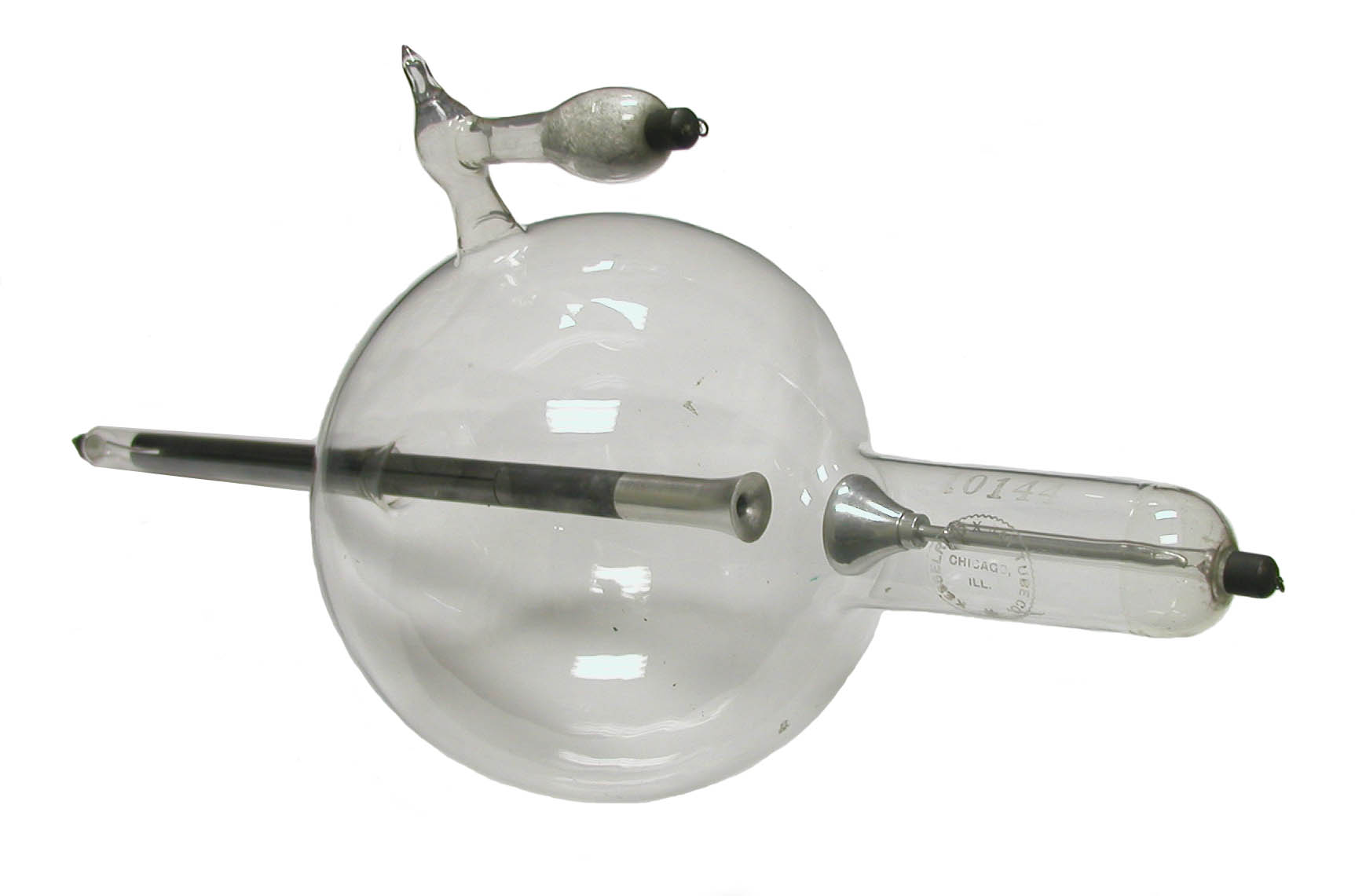
The tube's negative terminal is located at the tip of the glass arm projecting to the left (in the photo). Notice how the funnel-like anode extends out of this arm and almost all the way across the bulb.
The positive terminal is at the tip of the glass arm connected to the right side of the bulb. The aluminum cathode inside this arm is positioned where the latter connects to the bulb. In addition to the tube’s serial number "10144" and the manufacturer's name, the glass is etched "Patent Nov. 23, 1897" and “594,086” (the patent number). The same patent date and number sometimes appears on Kesselring tubes of very different design than this one.
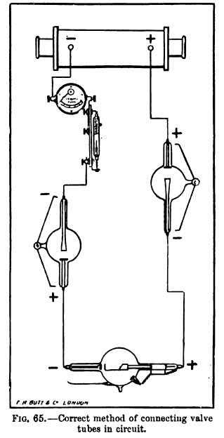
During use, a valve tube would be connected in series between the X-ray tube and the high voltage source. If a single valve tube was used, it might be connected to either the anode of the X-ray tube (before it) or the cathode (after it). It was also possible to employ two valve tubes as shown in the figure to the right (Knox, 1919): a valve tube connected to each end of the X-ray tube.
Since the resistance to the flow of current through the valve tube needed to be relatively low compared to that through the X-ray tube, the pressure of the residual gas in the valve tube was higher than in an X-ray tube, although it was still well below atmospheric pressure. And like the gas pressure in an X-ray tube, that in the valve tube tended to decrease over time. Hence the need for a regulator—the “L-shaped” glass appendage on the top of the tube.
I have not read a fully satisfying explanation of the physical process by which this type of valve tube works. Even the original patent for the funnel valve tube (Koch & Sterzel, 1905) makes no real attempt at an explanation. However, Ronne and Nielsen (1986) suggest two things.
First, they state that the static charge on the glass arm around the tube’s aluminum “anode” would minimize the emission of electrons from it during periods of reverse current. What bothers me about this explanation is that the same phenomenon should apply to the cathode of an X-ray tube, even though the latter is a strong source of electrons.
Their second explanation is related to the fact that the two electrodes of the valve tube are close together. What they say is this: during what would be a period of reverse current, what little electron flow there is would be from the valve tube’s anode (negatively charged during reverse flow) to the closest point on the funnel (now positively charged). The flow is minimal because the tip of the funnel lies within the “dark space” of the valve tube’s anode (now negatively charged and acting as the electron source). The weak flow of electrons generates insufficient ionization of the gas within this “dark space” for the current to significantly increase. However, when the current flows in the correct direction through the valve tube, many electrons are emitted from behind the tip of the funnel (the cathode) and therefore travel a relatively long distance to the anode. Because these electrons originate outside the cathode dark space, there is a greater ionization of the gas and therefore a greater current. Crystal clear.
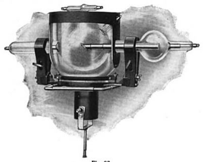
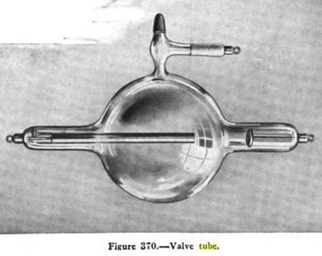
The figure above left (Raper, 1922) is quite interesting. It shows a dental X-ray tube and a valve tube combined together so that they share the same vacuum. Two tubes in one! The valve tube is incorporated as an extension of the X-ray tube's anticathode (target). The figure above right (Raper 1922) is somewhat less interesting, it simply shows a valve tube that is almost identical in appearance to the collection's Kesselring tube.
Kesselring X-ray was a relatively small operation founded by Hermann M. Kesselring, but I do not know exactly when. At various times they employed the following addresses in the Chicago area: 136 W. Lake Street, 652 W. Lake Street, and 204 N Desplaines Street. Their operations continued at least until 1921.
Size: Approximately 23" long with 7" bulb diameter
Kindly donated by Malvern J. Gross Jr. in memory of his father.
References
- Knox, R. Radiography and Radio-Therapeutics. Part I. 1919.
- Raper, H.R. Elementary and Dental Radiography. 1922.