Valve Tubes
The transformers used to provide the high voltage for X-ray systems require alternating current (AC). Since the induced current on the secondary side of the transformer is also AC, its polarity is constantly changing from positive to negative and back again—the frequency of the current is 60 cycles per second and the duration of a complete cycle is 1/60 of a second. In a given cycle, the potential is positive for 1/120 of a second and negative for 1/120 of a second.
This poses a potential (pun intended) problem for X-ray tubes since the latter are designed to operate with a specific polarity: a negative cathode and a positive anode (target). Electrons are supposed to go from the heated filament of the cathode to the anode (target) where the X-rays are produced. If the alternating current causes the potential across the tube to change so that the "cathode" is positive and the "anode" negative, there is the possibility that the electron stream in the tube could reverse so that X-rays were being produced by electrons striking the cathode. The result would be that the x-rays would no longer be focused since they were coming from two parts of the tube. In addition, the intensity and energy of the X-rays would vary.
The following diagram shows the two high voltage circuits for an x-ray system: one to provide the potential across the tube (with full wave rectification), and the other to provide the current to the filament. The former circuit controls the energy of the X-rays while the latter circuit controls the intensity of the x-rays.
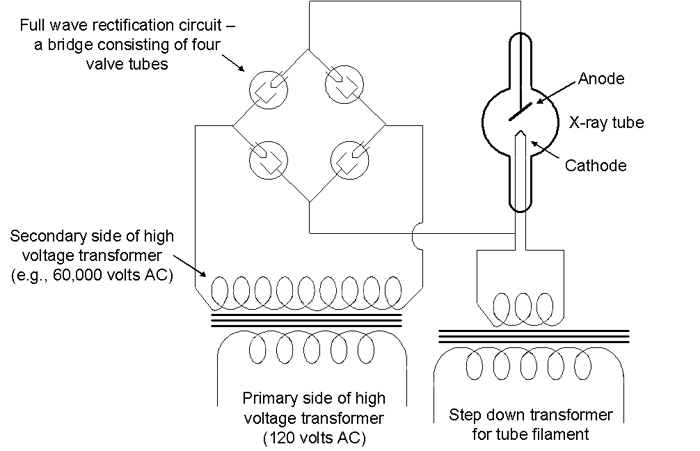
A step down transformer is used for the filament circuit to reduce the high voltage from 110/120 volts to 12 volts.
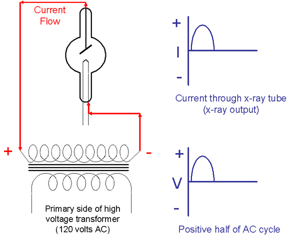
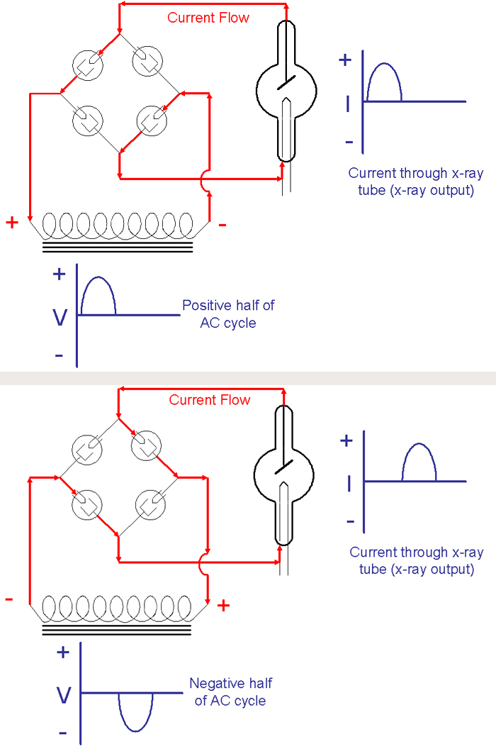
Since these Coolidge X-ray tubes employ a vacuum, electrons will not flow in the wrong direction from a negatively charged anode to a positive cathode unless the anode is hot enough to emit electrons. The anodes (targets) of radiator tubes, for example, never get hot enough for electrons to be ejected. As such, electrons can only flow in one direction and these tubes are said to be "self-rectifying." The following diagram shows the proper flow of electrons through a self-rectifying tube during the half of the AC cycle when the anode is positive and the heated cathode is negative. X-rays are emitted from the target.
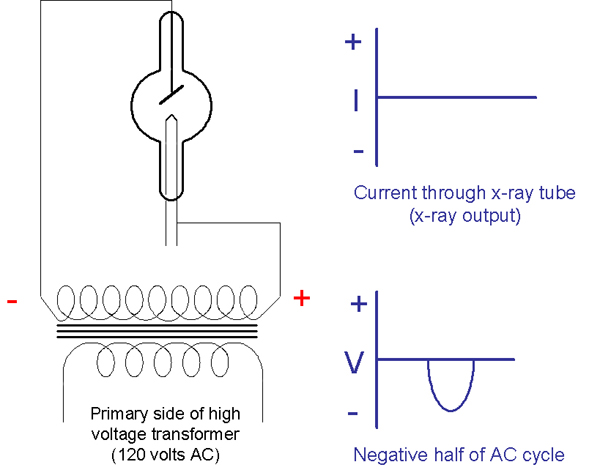
The following diagram shows that the electrons do not flow through a self-rectifying tube during the half of the AC cycle when the anode is negative and the heated cathode is positive. X-rays would not be emitted from the tube.
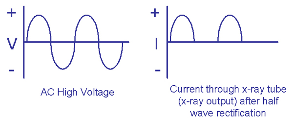
The following diagram shows the potential high voltage across a self-rectifying tube and the current through the tube during two complete cycles. This is half wave rectification.
Some tubes, the "Universal" tube for example, are not self-rectifying. To achieve the half-wave rectification shown above, a circuit employing two valve tubes (or solid state diodes) would be used.
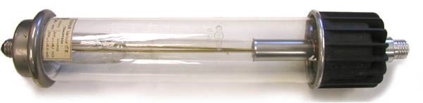
Valve tubes are essentially self-rectifying X-ray tubes that are designed to produce as low an intensity of X-rays as possible. The cathode is a central heated filament that is surrounded by a large annular anode. The electrons from the cathode are not focused and the strike the entire surface area of the anode. Since the latter never gets hot enough to emit electrons, current can only flow in one direction. In other words, it is a one-way valve!
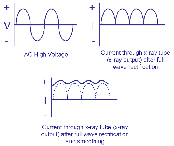
By using a bridge with four valve tubes in it, we can achieve full-wave rectification and double the tube's X-ray output. Such a full wave rectification circuit would work as indicated in the following two diagrams.
The following diagram shows the potential high voltage across a tube and the current through the tube during two complete cycles when a full wave rectification circuit is employed. It also shows how the range (ripple) of the tube current can be smoothed out by employing a capacitor in the tube circuit. An even smoother current with less ripple can be achieved by employing a three phase system. State of the art systems do even better and produce what is called a constant potential by employing high and medium frequency generators that rectify, smooth, chop and invert the high voltage on the primary side of the high voltage transformer.
-
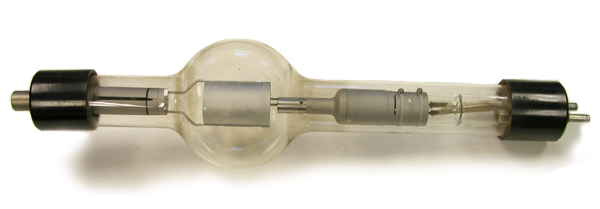
Eureka EV 3-75T Valve Tube Eureka EV 3-75T Valve Tube
-
General Electric KR-3 Kenotron Tube General Electric KR-3 Kenotron Tube
-
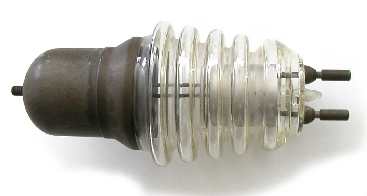
General Electric KR-7/8 Valve Tube General Electric KR-7/8 Valve Tube
-
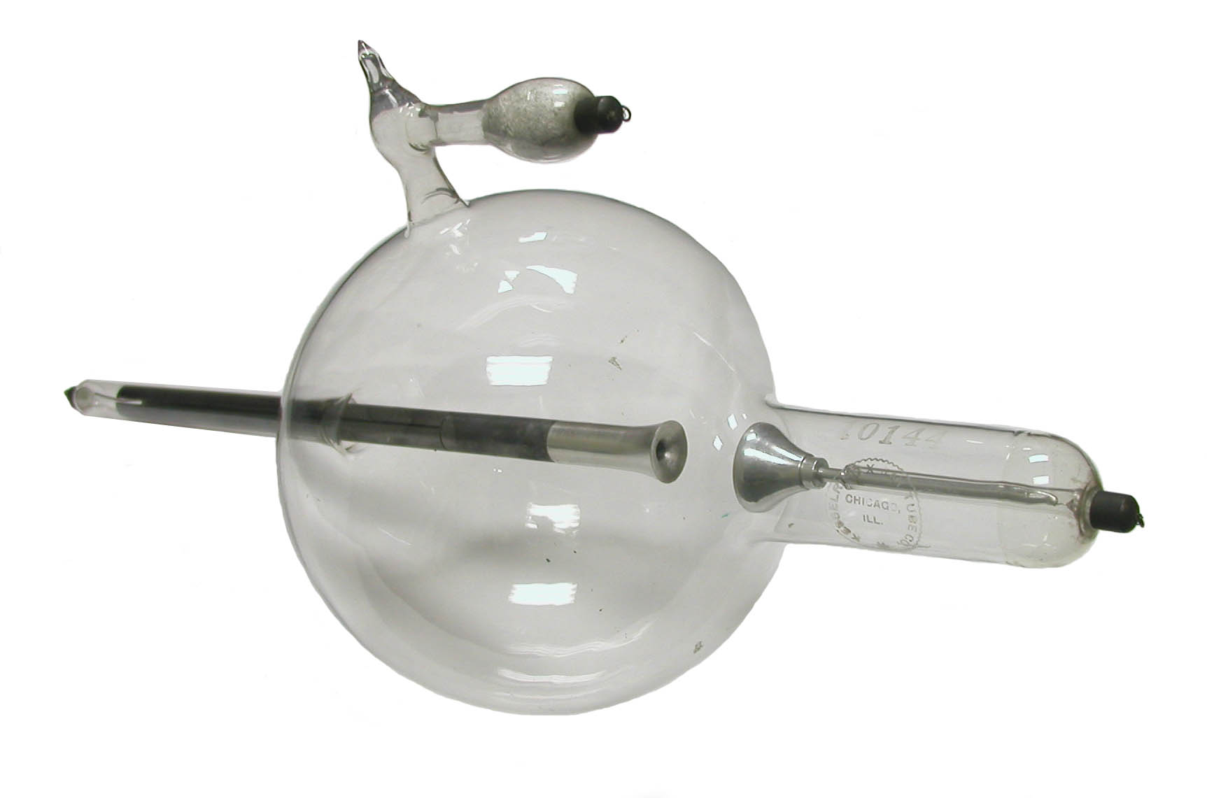
Kesselring Valve Tube Kesselring Valve Tube
-
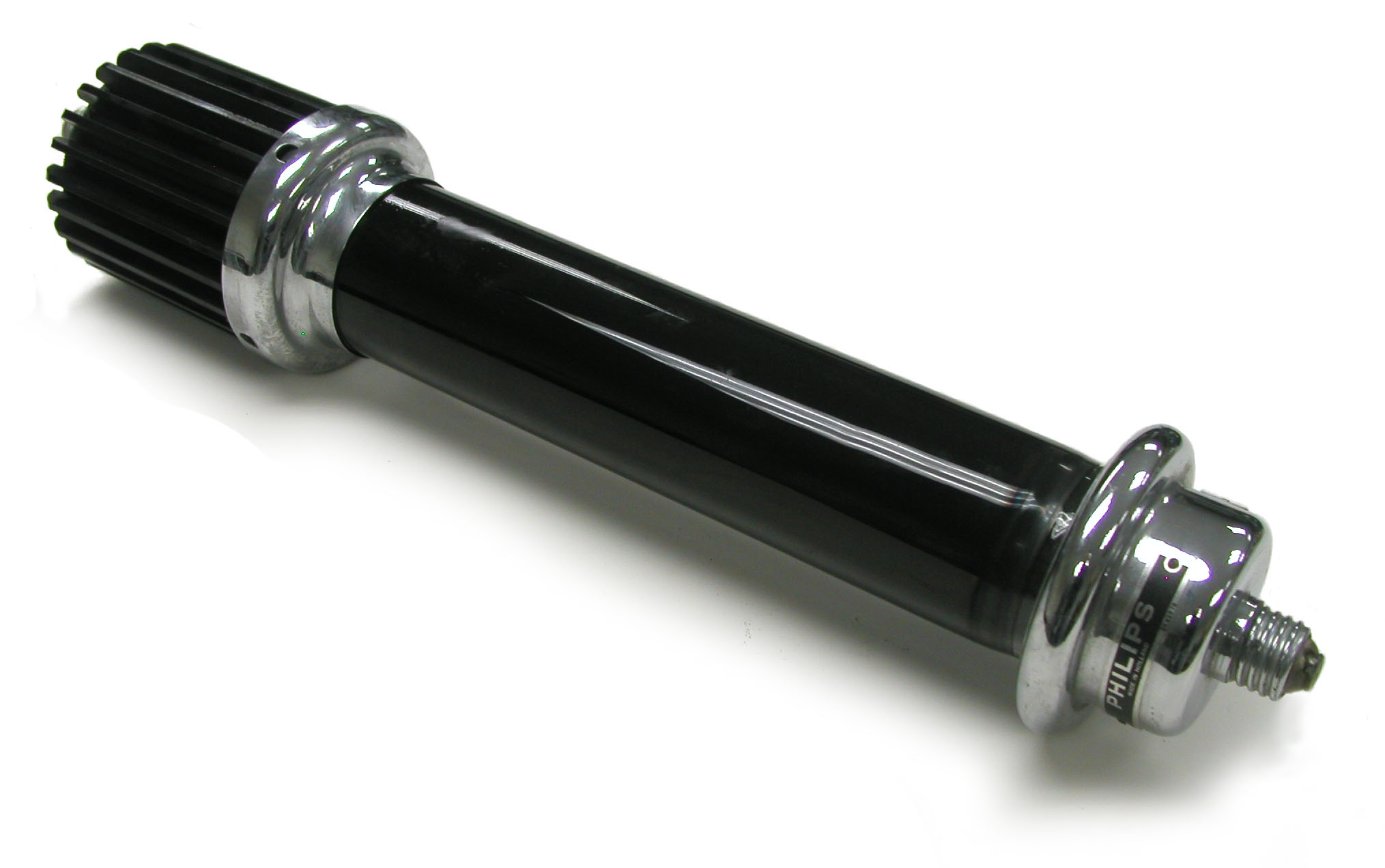
Philips Valve Tube - Model 28001/00 Philips Valve Tube - Model 28001/00
-
Tubix Kenotron, the "Valvix" Tubix Kenotron, the "Valvix"