Coolidge X-Ray Tubes
Introduction
Without a doubt, the single most important event in the progress of radiology was the invention by William Coolidge in 1913 of what came to be known as the Coolidge X-ray tube. Nevertheless, despite its clear superiority, the Coolidge tube did not immediately replace cold cathode tubes—the latter continued to be manufactured into the 1920s and saw routine use into the 1930s. In fact, there were instances of cold cathode tubes being employed in radiology as late as the 1960s!
If you are interested in the details of Cooludge tube production, the 1920 paper Manufacture of the Coolidge X-ray Tube by Robinson and Moore is worth a read.
The characteristic features of the Coolidge tube are its high vacuum and its use of a heated filament as the source of electrons. There is so little gas inside the tube that it is not involved in the production of X-rays, unlike the situation with cold cathode gas discharge tubes.
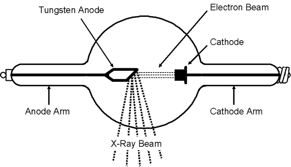
The operation of the Coolidge tube is as follows. As the cathode filament is heated, it emits electrons. The hotter the filament gets, the greater the emission of electrons. These electrons are accelerated towards the positively charged anode and when the electrons strike the anode, they change direction and emit bremsstrahlung, i.e., X-rays with a continuous range of energies. The maximum energy of the X-rays is the same as the kinetic energy of the electrons striking the anode. In addition to the X-rays produced at the focal spot of the anode, some undesirable X-rays (stray radiation) are produced by electrons striking other tube components.
The key advantages of the Coolidge tube are its stability, and the fact that the intensity and energy of the X-rays can be controlled independently. Increasing the current to the cathode increases its temperature. This increases the number of electrons emitted by the cathode, and as a result, the intensity of the X-rays. Increasing the high voltage potential difference between the anode and the cathode increases the velocity of the electrons striking the anode, and this increases the energy of the emitted X-rays. Decreasing the current or the high voltage would have the opposite effects. The high degree of control over the tube output meant that the early radiologists could do with one Coolidge tube what before had required a stable of finicky cold cathode tubes. As a bonus, the Coolidge tube could function almost indefinitely unless broken or badly abused.
The Shape of the Tube
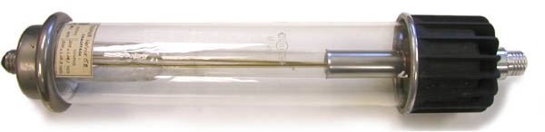
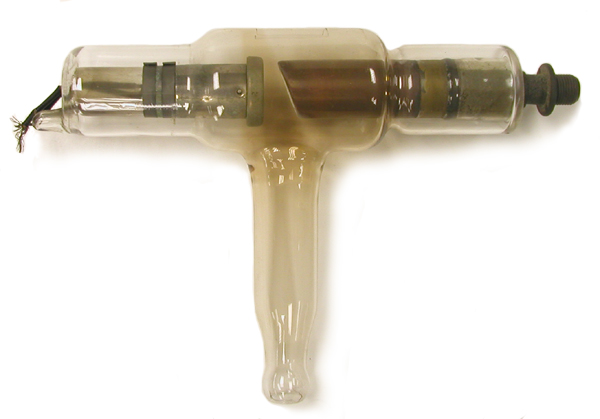
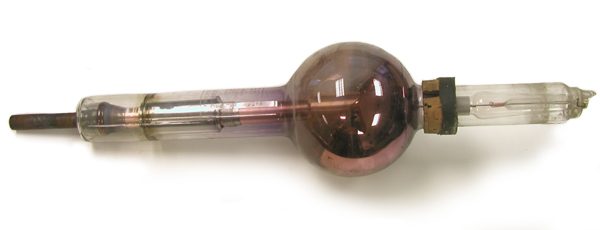
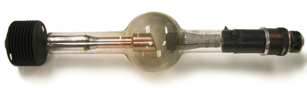
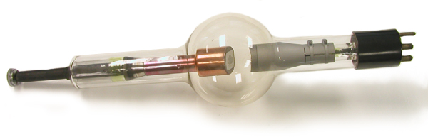
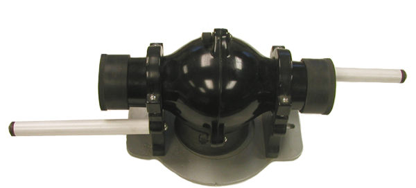
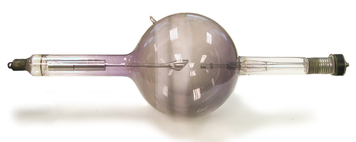
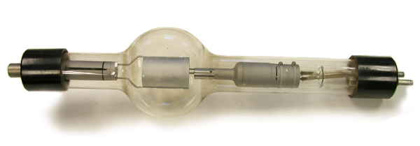
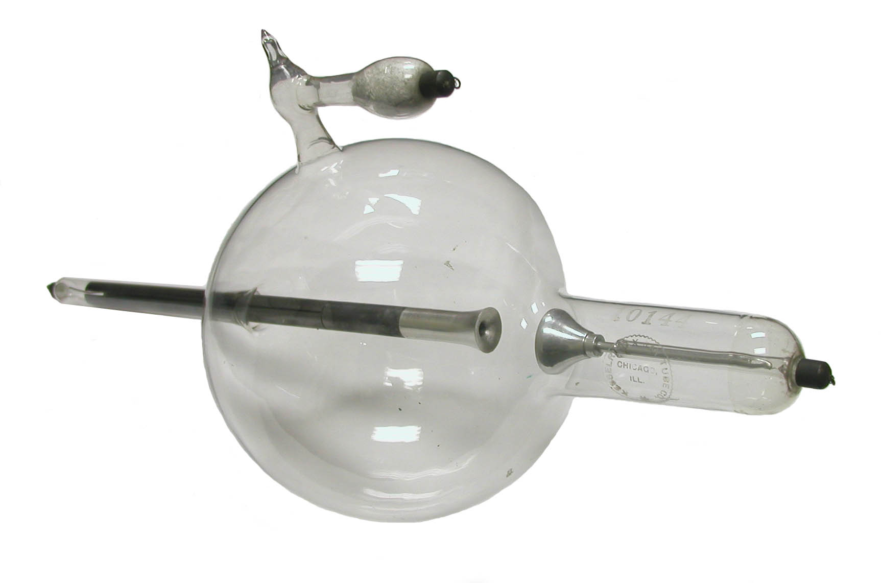
The basic shape of the original Coolidge tube consisted of a spherical bulb with two cylindrical arms extending out on opposite sides: the cathode arm and the anode arm. The arms increase the dimensions of the tube so as to avoid electrical arcing from one end to the other. The length of the arms also helps prevent stray electrons on the inside of the tube from getting close to the tube ends.
The bulb is large so as to increase the surface area through which the tube radiates heat (to limit the glass temperature). In addition, its large size reduces the amount of tungsten that can be deposited per unit area, and it keeps the glass away from the strongest portion of the electrostatic field—the longitudinal electrostatic stresses in tubes with a conductive layer of tungsten deposited on the inner surface could negatively affect a tube’s operation. If the tube incorporates another mechanism by which heat can be dissipated (other than simple radiation through the glass envelope), the bulb can be made smaller.
The hard glasses (e.g., Pyrex) that began to be used in the 1930s had a sufficiently high dielectric strength and heat resistance that the bulb could be eliminated and the tubes made completely cylindrical. This was advantageous because shielding a cylindrical tube was a simple proposition.
The Anode
Tungsten is the most commonly used target material in the anode because it has a high atomic number which increases the intensity of the X-rays, and because it has a sufficiently high melting point that it can be allowed to become white hot. During operation, the tungsten target can get as high as 2,700 degrees centigrade. In many cases, the tungsten target is surrounded by copper—the high heat capacity of copper improves the dissipation of heat.
The area over which the electrons from the cathode strike the anode is referred to as the focal spot. The cooler the anode can be kept, the smaller the focal spot can be and the greater the image detail that is possible. If a high x-ray output is required, a larger focal spot would be needed to mitigate the temperature increase.
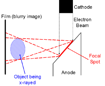
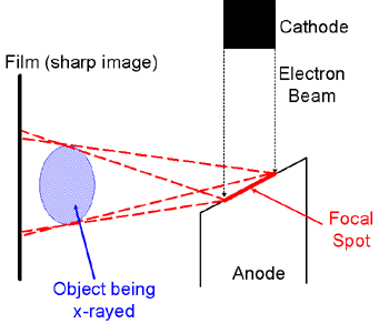
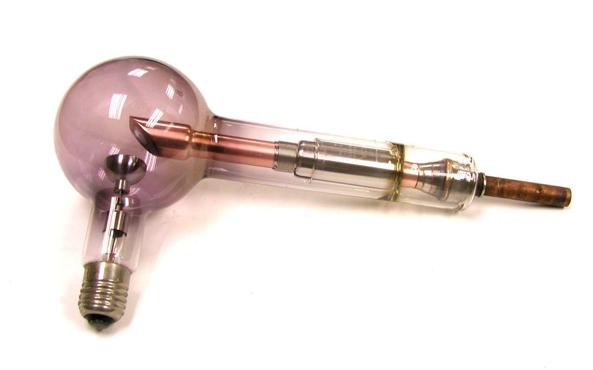
In the early tubes the angle of the target was usually 45 degrees (see figure below left). Later tubes often employed the so-called line-focus principle in which the target angle was closer to 20 degrees (see figure below right). This reduced the effective area of the focal spot (as viewed from the perspective of the object being X-rayed) without significantly affecting the area of the anode bombarded by the electron beam from the cathode. In other words, it permitted high loading (X-ray intensity) without having to sacrifice image detail.
Some degree of cracking and pitting of the focal spot is normal, especially in tubes with a large focal spot. Fortunately this doesn't affect the tube's performance unless the damage is so severe that the ability of the anode to dissipate heat is compromised. At least in some cases, a tungsten-rhenium alloy has been used in the construction of the anode to reduce the cracking and pitting, as well as reduce the evaporation of tungsten onto the tube envelope.
The Cathode
The cathode of the Coolidge tube incorporates a wound tungsten filament that emits electrons when heated. There are two general configurations of the filament. Either the spiral tungsten wire takes a circular/conical form (typical of the "Universal" tubes) or it is shaped like an elongate coil (the so-called Benson design).
The filament is located in a cylindrical chamber or slot machined into in the cathode. As a rule, the focal spot is similar in size and shape (either round or elongate) to this opening.
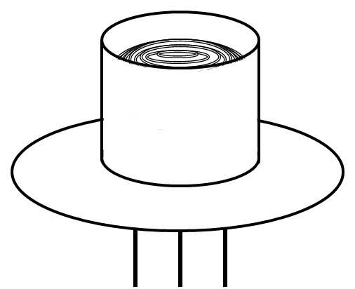
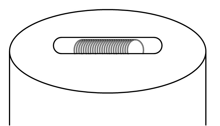
The size and shape of the focal spot is partly determined by the filament's position relative to the other components of the cathode. The focal spot size can be reduced by positioning the filament deeper in the slot (or opening) in the cathode, or increased by moving the filament closer to the top of the opening.
Dual focus tubes employ cathodes with two filaments: one small, the other large. Each filament is positioned in its own slot. The smaller filament produces a small focal spot for fine focus work. The larger filament, which produces a broader focal spot, is employed when faster exposures (higher intensities) are required. These dual focus tubes usually have a switch at the end of the cathode arm that is used to select the desired focal spot.
A step down transformer is used to reduce the line voltage from 110 volts to the 12 volts required for the tube filament. The current to the filament is adjusted with either a Rheostat (resistance) or Inductance type regulator. An ammeter is employed to measure the current used to heat the filament—the current serves as a measure of the intensity of the X-rays that are being produced.
To help prevent cold cathode discharges that can result in erratic performance of the tube, the electrodes are smooth and rounded. Such discharges are more likely when very high voltages are used with tubes in which the anode and cathode are closely spaced.
The Glass
Although the envelopes of X-ray tubes can be made of metal, glass is more popular because it is a good insulator, it is vacuum tight, it has a relatively high melting point, it does not seriously attenuate the X-rays, and it can be fabricated into a wide range of shapes. The early tubes (e.g., pre 1930) were made from soft glass containing sodium or cerium. Later tubes tended to use hard borosilicate glass even though it was more difficult to work with. Borosilicate glass has the advantages of a greater dielectric strength and higher melting point. The latter means that the tubes could be more effectively degassed and evacuated. Because borosilicate glass walls were thicker than those made from softer glass, a window had to be created by grinding down that region of the glass wall that the X-rays needed to penetrate.
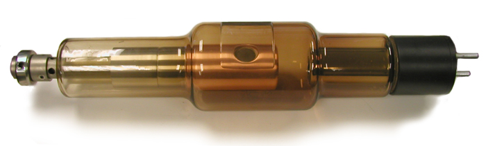
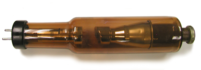
With use, the clear colorless glass of an X-ray tube can become colored. Such a color change is either due to the absorption of radiation energy, or the deposition of tungsten on the inside surface of the glass. The absorption of X-ray energy by electrons in the glass promotes them to a higher energy state (the conduction band). The now mobile electrons move to positively charged impurities in the glass where they become trapped. Since these trapped electrons are at a higher energy level than they were prior to the exposure to radiation, the absorption spectrum and the color of the glass is affected. The resulting color depends on the type of the impurities: the softer glass of the older tubes (e.g., 1920s vintage) tended to turn purple, while the harder glass of the more modern tubes (e.g., post 1930) tended to take on an amber color.
Just as tungsten can be deposited on the inside surface of an incandescent light bulb, tungsten can be deposited on the inside surface of the envelope of an X-ray tube. If this deposition is significant, the tube was probably operated beyond its rated capacity. In extreme cases, the deposition can be sufficiently great that it gives the glass a mirrored appearance. A problem with an excessive accumulation of tungsten is that the inside of the glass becomes conductive and allows electrons to leak across the glass surface. This makes the tube more susceptible to puncture.
In addition, the accumulation of electrons on the inside of the glass can distort the flow of electrons from the cathode towards the anode. It can also produce a static charge that attracts dust onto the outer surface of the tube. If this dust absorbs moisture from the air, the outer surface of the tube becomes conductive and this increases the possibility that sparks will be produced that can puncture the tube’s envelope. Tubes designed for therapy required thicker glass than diagnostic tubes because the higher voltages at which they operated produced a greater potential difference between the negatively charged inside of the glass and the outside of the glass. If the glass was too thin, the charge would break through the glass and puncture it.
When operated at low voltages, the glass envelope might fluoresce. The color of the fluorescence depends on the type of the glass: soft and hard glass usually exhibited a green and blue fluorescence respectively.
The wire penetrating the glass seals at the end of the tube is what was known as Dumet wire, a copper-coated alloy of nickel and iron that had the same coefficient of expansion as the glass.
Shock-Proof Systems
The electrical cables providing high voltage and current to the early (pre 1930 or so) X-ray systems used bare uninsulated wire. The reason for this was that insulated wire could duplicate a choke-coil and limit the filament current. As a result, early radiologists had to be very careful to avoid electrocution. The first completely shock-proof X-ray system seems to have been a dental X-ray unit developed in 1921 by William Coolidge—the high voltage system and tube was immersed in a grounded metal tank filled with oil.
Immersing the tube in oil not only improves cooling, it reduces the potential for leakage current across the tube surface, and this means that the tube can be made shorter. It also reduced the effect of altitude and humidity on tube performance (altitude and humidity affect the cooling capability of air).
References
- C. Jerman. Modern X-Ray technic.Bruce Publishing Co. St.Paul. 1928.
- R.L. Eisenberg. Radiology – An Illustrated History. Mosby. St. Louis. 1991.
- W.D. Coolidge. The development of modern roentgen-ray generating apparatus. Am. J. Roentgenology. 24: 605-620. 1930.
- M.J. Gross, Z.J. Atlee. Progress in the design and manufacture of x-ray tubes. Radiology 21:365-377; 1933.
Miscellaneous X-Ray Tubes
-
Collimated Low Energy Therapy Tube Collimated Low Energy Therapy Tube
-
General Electric CA-2 X-ray Diffraction Tube General Electric CA-2 X-ray Diffraction Tube
-
General Electric D-1.7 X-ray Tube General Electric D-1.7 X-ray Tube
-
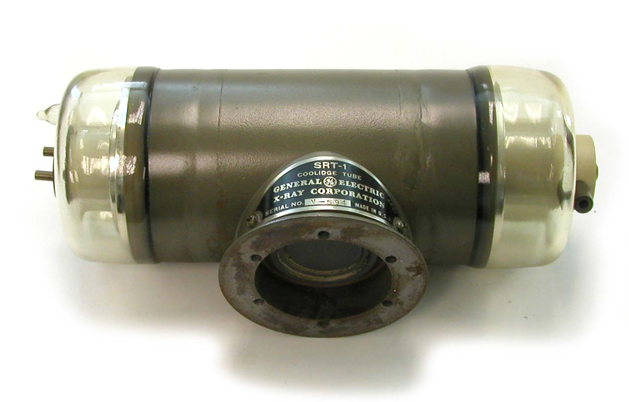
General Electric SRT-1 X-ray Tube General Electric SRT-1 X-ray Tube
-
General Electric SRT-2 X-ray Tube General Electric SRT-2 X-ray Tube
-
General Electric XP1-4 and XP2-4.5 Tubes General Electric XP1-4 and XP2-4.5 Tubes
-
General Electric XPD Tube General Electric XPD Tube
-
Machlett CW-250-T Tube Machlett CW-250-T Tube
-
Westinghouse WL-395 Tube Westinghouse WL-395 Tube
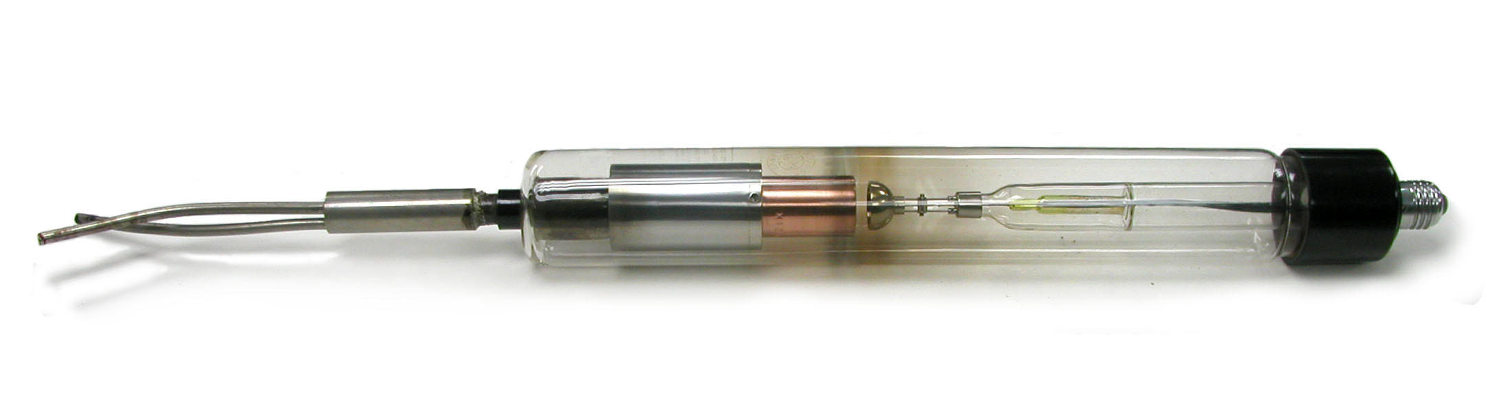
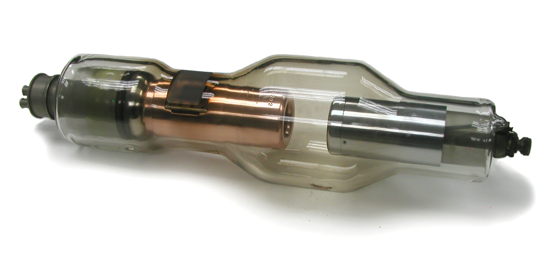
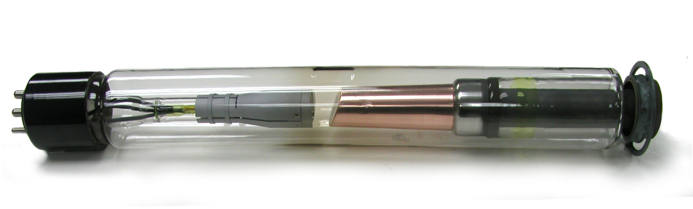
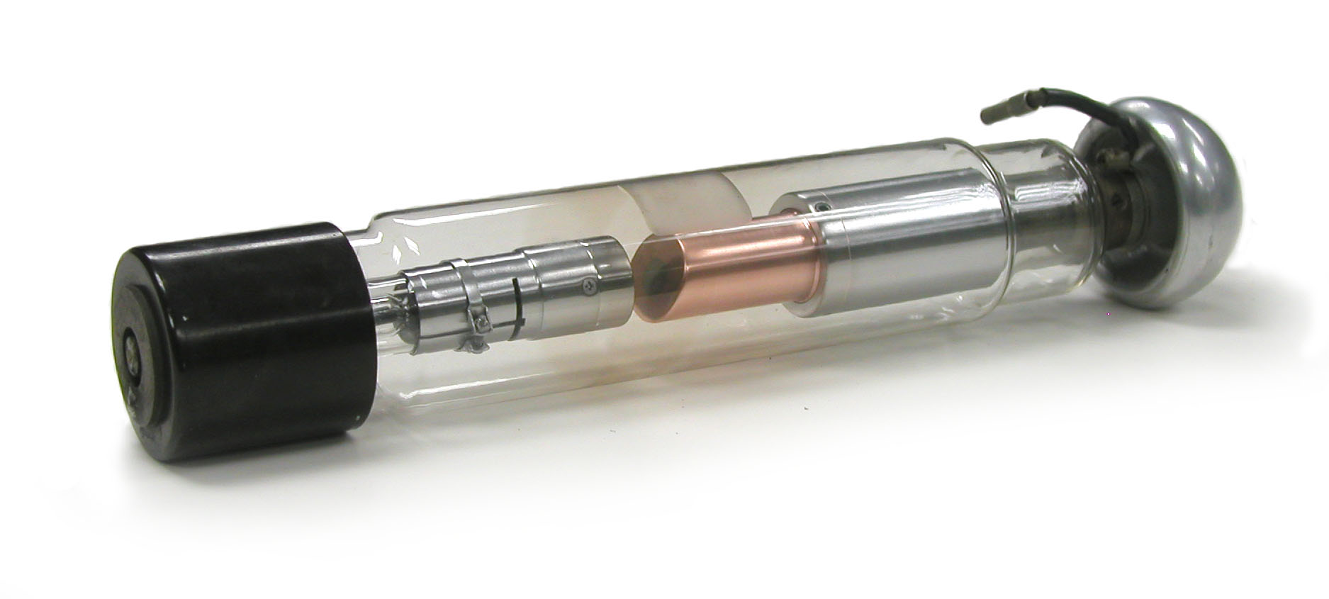
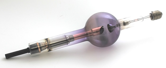
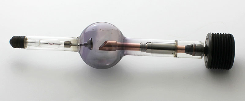
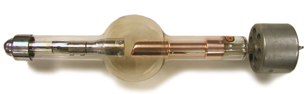
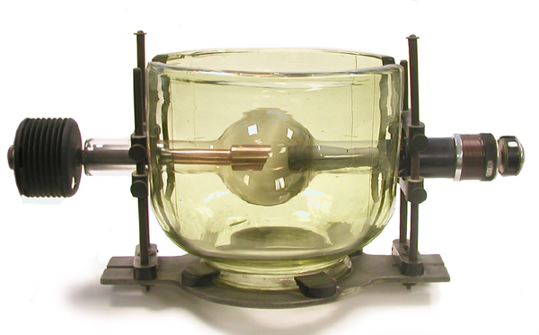
Radiator Coolidge X-ray Tubes
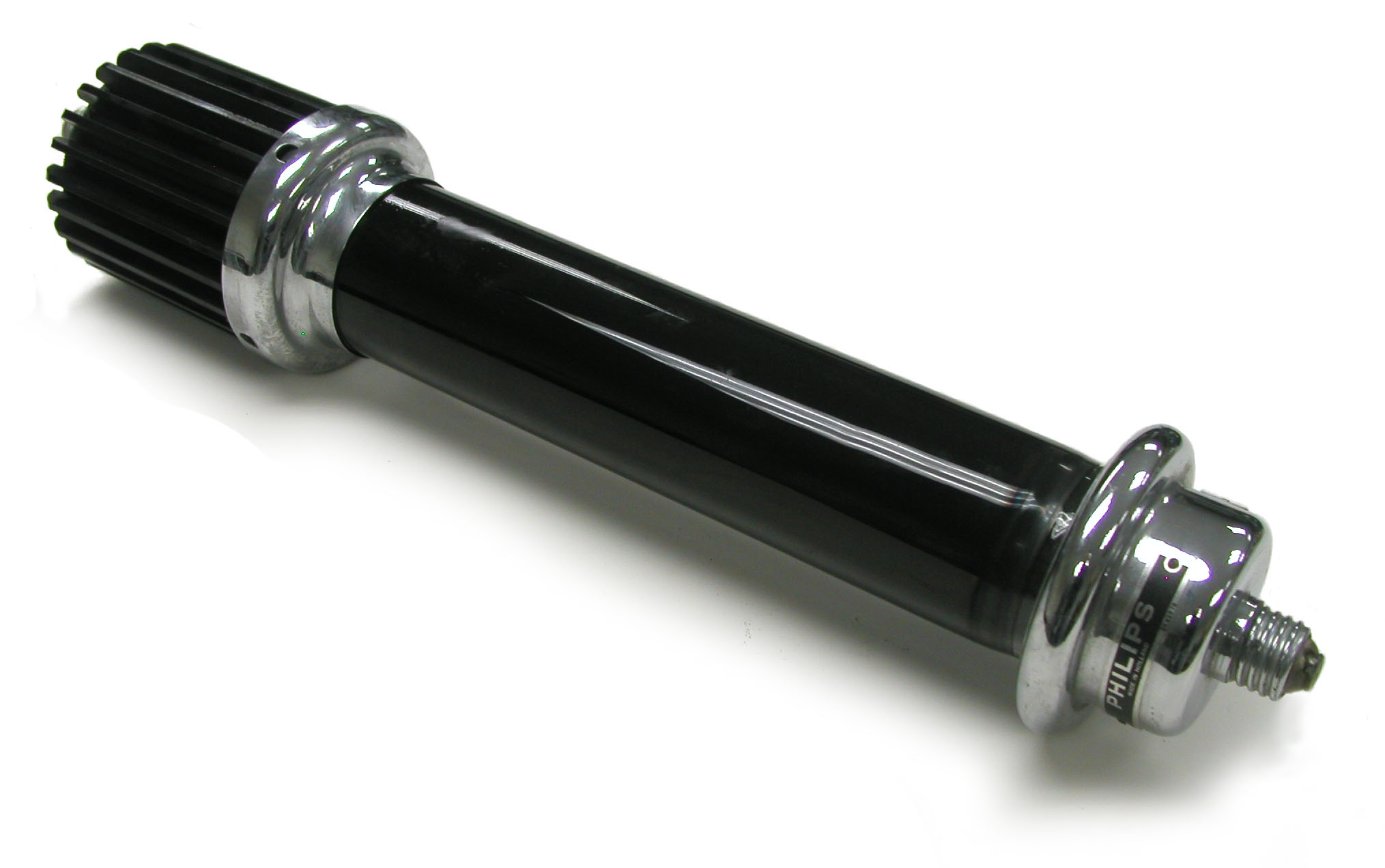
To learn about Coolidge Radiator tubes, you couldn't do much better than read William Coolidge's 1919 paper The Radiator Type of Tube—radiator tubes (and universal tubes) were first produced by the General Electric Company. Perhaps the most obvious difference between the radiator type tube (sometimes referred to as an “R” tube) and the Universal tube is that the former radiates its excess heat through an external radiator (e.g., with copper fins) whereas the latter radiates heat through the glass envelope of the tube. Because the glass of the radiator tube doesn’t get as hot as that of the Universal tube, its bulb can be smaller (all other things being equal). Another obvious difference is that the anode of the radiator tube is a tungsten disk embedded in a copper head. The latter is attached to a copper rod which, in turn, is connected to the radiator. Radiator tubes were almost exclusively used for diagnostic work whereas universal tubes were for therapeutic as well as diagnostic use.
The two most common types of Radiator tubes are the fine focus and the medium focus tubes. The former had a maximum current limit of 10 milliamps with a 5” spark gap (various reports equated a 5” spark gap to a 56,000 or 88,000 volt potential) and it could be operated continuously for up to 30 seconds. Since this tube had the smaller focal spot (7/64 to 10/64 inch), fine image detail was possible. The other common type of Radiator tube had a 30 milliamps rating with a 5” spark gap. It could be operated continuously for up to 20 seconds. This tube had a relatively large focal spot (11/64 to 15/64 inch), which sacrificed image detail but permitted shorter exposures. A less common radiator tube, rated for a 100 milliamp current with a 5” spark gap, had a large focal spot (14/64 to 20/64 inch) and could be operated continuously for up to 5 seconds at the rated current.
The type of tube was sometimes indicated according to the spark gap and the maximum rated current as follows: 5-10, 5-30 and 5-100.
An advantage of the Radiator tube was that it could be operated without a rectified current because it is self-rectifying. If unrectified AC current were used, electron emission from the tungsten target is not possible during the half of the cycle when the target (anode) has a negative charge and the “cathode” has a positive charge. This is because the temperature of the tungsten target does not get hot enough for it to emit electrons.
References
- C. Jerman. Modern X-Ray technic. Bruce Publishing Co. St.Paul. 1928.
- R.L. Eisenberg. Radiology – An Illustrated History. Mosby. St. Louis. 1991.
- W.D. Coolidge. The development of modern roentgen-ray generating apparatus. Am. J. Roentgenology. 24: 605-620. 1930.
- M.J. Gross, Z.J. Atlee. Progress in the design and manufacture of x-ray tubes. Radiology: 365-377; 1933.
-
General Electric Radiator Tube General Electric Radiator Tube
-
General Electric RB-1-4 Radiator Tube General Electric RB-1-4 Radiator Tube
-
General Electric RB-2-4.5 Radiator Tube General Electric RB-2-4.5 Radiator Tube
-
Victor RD Dental X-ray Tube Victor RD Dental X-ray Tube
-
Victor X-Ray Corporation 10 MA Radiator Tube Victor X-Ray Corporation 10 MA Radiator Tube
-
Victor X-Ray Corporation 30 MA Radiator Tube Victor X-Ray Corporation 30 MA Radiator Tube
-
Westinghouse 2249 Tube Westinghouse 2249 Tube
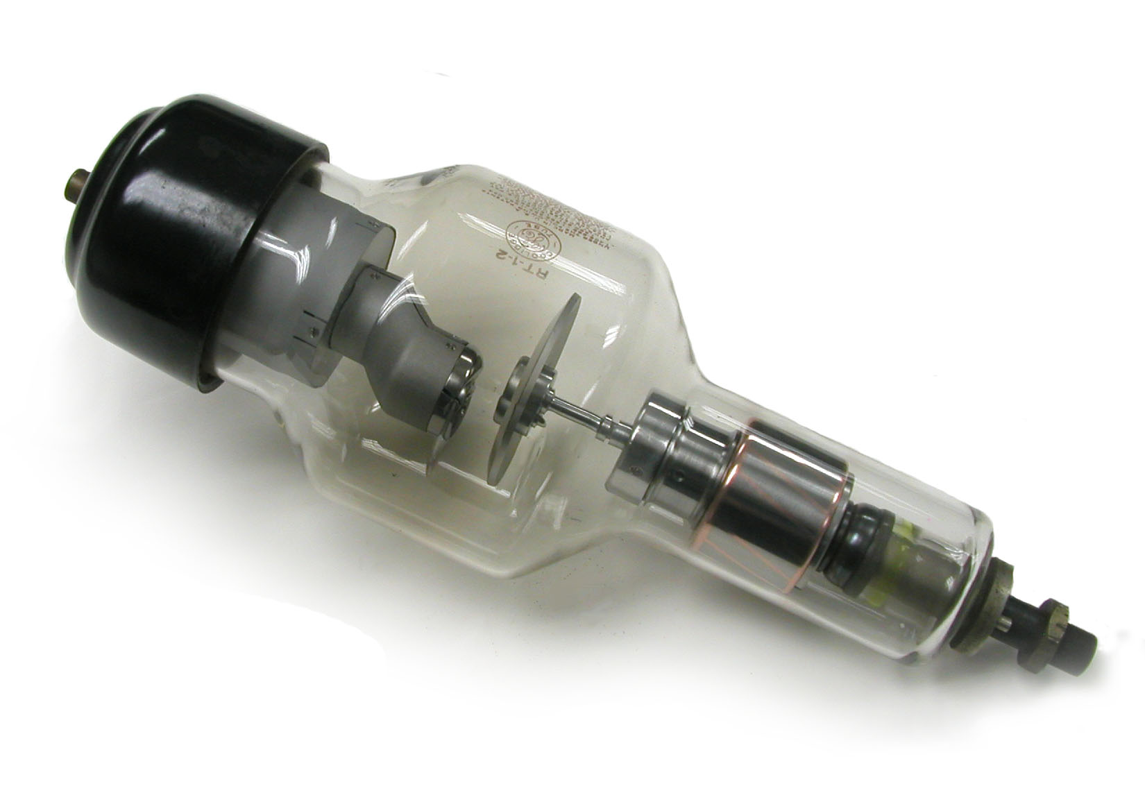
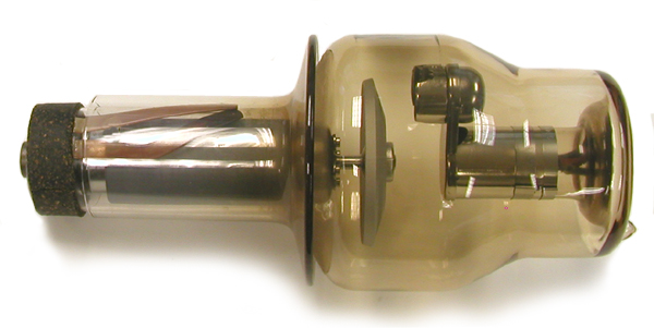
Rotating Anode Tubes
During operation, a large disk-shaped tungsten anode is rotated at high speed (3000 to 9000 revolutions per minute). The motive force for the rotation is provided by an induction motor the windings of which are housed outside the tube. Although the focal spot of the electrons impinging on the anode is no larger than that in a tube with a stationary anode, the effective area of the anode exposed to the beam is much larger. By this means, the heating of the anode is reduced and the tube loading can be increased (e.g., up to 500 mA with a 2 mm x 2 mm focal spot).
One of the tricky problems that had to be overcome in building these tubes was how to lubricate the tube's moving components—wet lubricants could not be used because of the vacuum.
According to Richard Mould, the concept of the rotating anode X-ray tube originated with Elihu Thomson in 1896. Others have suggested that it was Robert Wood in 1897. Either way, it was some time before a working model could be constructed. The first practical working version seems to have been described by General Electric's William Coolidge in 1915. Quoting the latter's paper in the December 1915 issue of the American Journal of Roentgenology, the tube had a "target rotation of 750 revolutions per second with the focal spot describing a circle 0.75" (19 mm) in diameter. 2.5 times as much energy for the size of the focal spot is obtained when compared with the stationary target."
Philips of Holland, not General Electric, produced the first commercially available rotating anode tube, the Rotalix. It came out in 1929, and Eureka obtained the license to produce it in the U.S. Soon, General Electric and Machlett came out with their own versions. Still, these early tubes had their problems, and it wasn't until the 1940s that rotating anode tubes finally came into their own. By the 1950s or so they had become the standard tube design for diagnostic work.
References
- Etter, L.E. The Science of Ionizing Radiation. Charles C Thomas. 1965.
- Grigg, E.R. The Trail of the Invisible Light. Charles C Thomas. 1965.
- Mould, R. A Century of X-rays and Radioactivity in Medicine. Institute of Physics Publishing. Bristol. 1993.
-
General Electric RT-1-2 Rotating Anode Tube General Electric RT-1-2 Rotating Anode Tube
-
Machlett FDX 1-2 Rotating Anode Tube Machlett FDX 1-2 Rotating Anode Tube
Shields/Protective Housings
-
General Electric/Victor Protective Cover General Electric/Victor Protective Cover
-
Leaded Glass Bowl Leaded Glass Bowl
-
Leaded Glass Shield Leaded Glass Shield
-
Leaded Glass Shield Leaded Glass Shield
-
Philips/Muller Metalix Housing with Water Cooling Assembly Philips/Muller Metalix Housing with Water Cooling Assembly
-
Protective Housing for X-ray Tube Protective Housing for X-ray Tube
-
Radiologie "Protecta" Tube Housing Radiologie "Protecta" Tube Housing
-
Shock Proof Dental X-ray Tube Shock Proof Dental X-ray Tube
-
Siemens Multix Protective Housing with Water Cooling Assembly Siemens Multix Protective Housing with Water Cooling Assembly
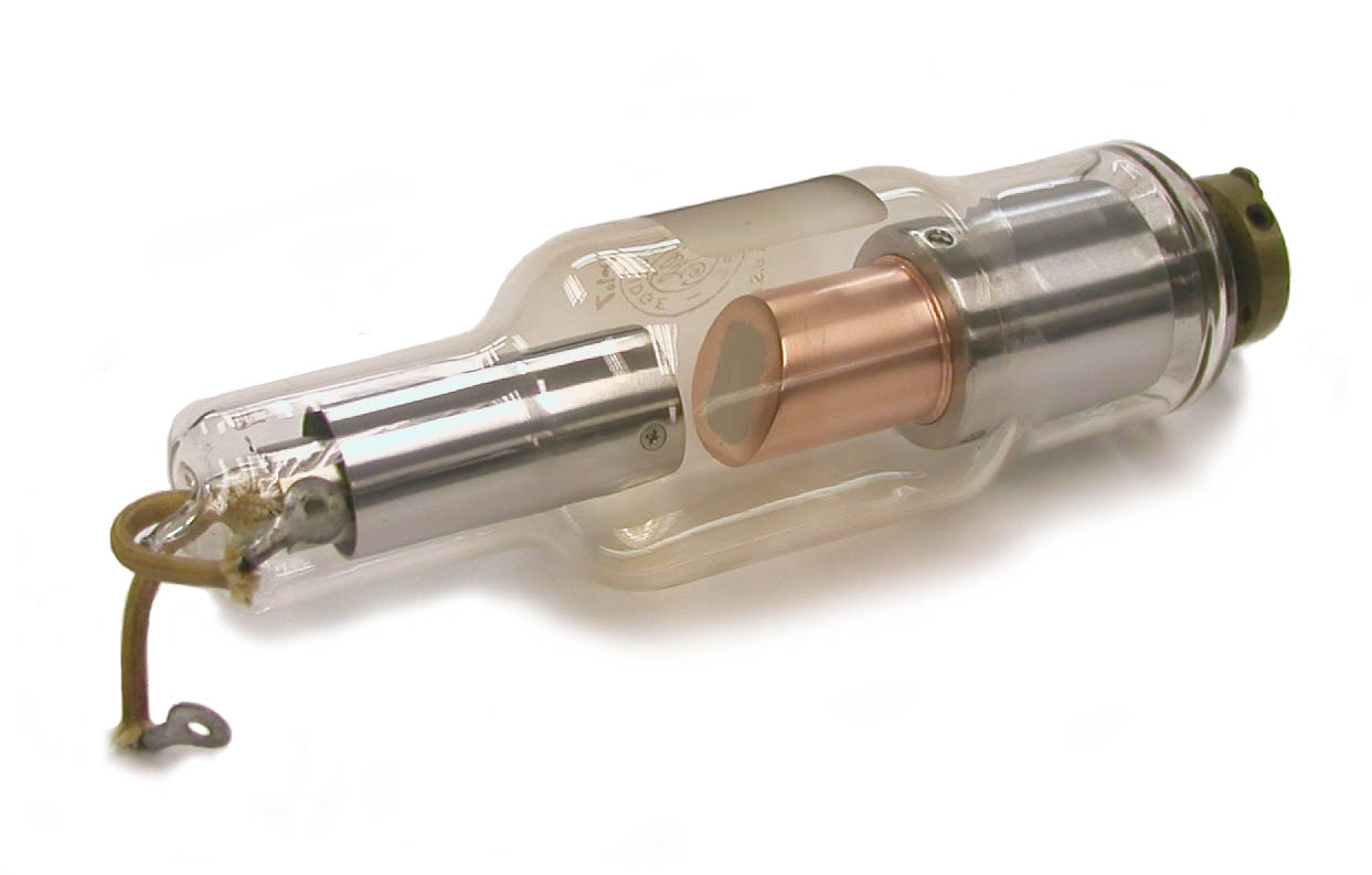
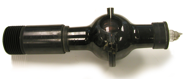
Universal X-Ray Tubes
The Universal Tube was so named because it could be used in almost any application, e.g., diagnostic X-rays (roentenography), fluoroscopy and therapy as well as various non-medical uses. In essence, it is the original Coolidge tube with a few minor modifications.
During operation, the heat from the anode is radiated out through the bulb of the tube. So that the glass won’t overheat, the bulb has to be kept fairly large: ca. 6-7” in diameter.
The threaded screw-in connector at the end of the cathode arm is the same as that employed with a light bulb. This reflects the fact that William Coolidge’s inspiration for the hot cathode X-ray tube was his earlier work developing tungsten filaments for incandescent lights.
The anode is solid tungsten and it is attached to a molybdenum stem. The latter, in turn, is connected to a split metal tube that helps provide support.
There were three variations on the Universal tube: those with a fine focal spot, those with a medium focal spot, and those with a broad focal spot. The cathode filament of the fine focus version forms a flat spiral near the end of a short molybdenum tube, while that of the medium and broad focal spot tubes forms a slightly conical spiral.
The following table indicates the ratings for these tubes.
| Tube Type | Maximum Voltage | Equivalent Spark Gap | Maximum Current | Continuous use limit |
|---|---|---|---|---|
|
Fine Focus |
100,000 |
6” |
25 mA |
20 seconds |
|
Medium Focus |
100,000 |
6” |
40 mA |
15 seconds |
|
Broad Focus |
100,000 |
6” |
80 mA |
5 seconds |
|
Broad Focus |
140,000 |
10” |
5 mA |
continuous |
The fine and medium focus tubes were better for general radiographic work. The broad focus Universal tube was best suited for therapeutic use because of its greater potential output. When the broad focus tube was operated at very high voltages, it would have been particularly important to keep the tube clean and far enough away from metal objects to prevent sparking.
The Universal tube needed to be operated with a rectified current. If unrectified AC current were used, electron emission from the tungsten target would be possible during the half of the cycle when the target ("anode") had a negative charge and the “cathode” a positive charge. This could only occur if the target had been heated to the point that it emitted electrons.
References
- E. C. Jerman. Modern X-Ray technic. Bruce Publishing Co. St.Paul. 1928.
- Radiology – An Illustrated History.
- W.D. Coolidge. The development of modern roentgen-ray generating apparatus. Am. J. Roentgenology. 24: 605-620. 1930.
- M.J. Gross, Z.J. Atlee. Progress in the design and manufacture of x-ray tubes. Radiology:365-377; 1933.
-
General Electric Universal X-ray Tube General Electric Universal X-ray Tube
-
Victor X-Ray Corp. Universal X-ray Tube Victor X-Ray Corp. Universal X-ray Tube
Valve Tubes
The transformers used to provide the high voltage for X-ray systems require alternating current (AC). Since the induced current on the secondary side of the transformer is also AC, its polarity is constantly changing from positive to negative and back again—the frequency of the current is 60 cycles per second and the duration of a complete cycle is 1/60 of a second. In a given cycle, the potential is positive for 1/120 of a second and negative for 1/120 of a second.
This poses a potential (pun intended) problem for X-ray tubes since the latter are designed to operate with a specific polarity: a negative cathode and a positive anode (target). Electrons are supposed to go from the heated filament of the cathode to the anode (target) where the X-rays are produced. If the alternating current causes the potential across the tube to change so that the "cathode" is positive and the "anode" negative, there is the possibility that the electron stream in the tube could reverse so that X-rays were being produced by electrons striking the cathode. The result would be that the x-rays would no longer be focused since they were coming from two parts of the tube. In addition, the intensity and energy of the X-rays would vary.
The following diagram shows the two high voltage circuits for an x-ray system: one to provide the potential across the tube (with full wave rectification), and the other to provide the current to the filament. The former circuit controls the energy of the X-rays while the latter circuit controls the intensity of the x-rays.
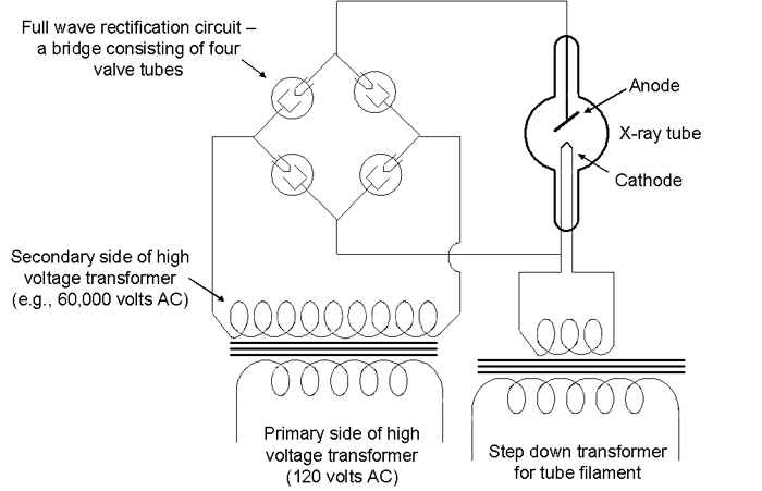
A step down transformer is used for the filament circuit to reduce the high voltage from 110/120 volts to 12 volts.
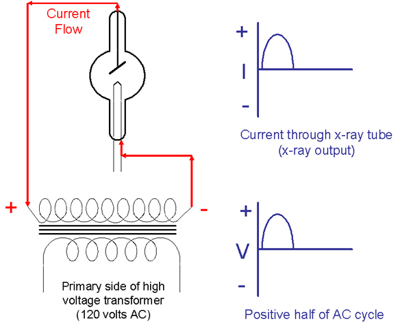
Since these Coolidge X-ray tubes employ a vacuum, electrons will not flow in the wrong direction from a negatively charged anode to a positive cathode unless the anode is hot enough to emit electrons. The anodes (targets) of radiator tubes, for example, never get hot enough for electrons to be ejected. As such, electrons can only flow in one direction and these tubes are said to be "self-rectifying." The following diagram shows the proper flow of electrons through a self-rectifying tube during the half of the AC cycle when the anode is positive and the heated cathode is negative. X-rays are emitted from the target.
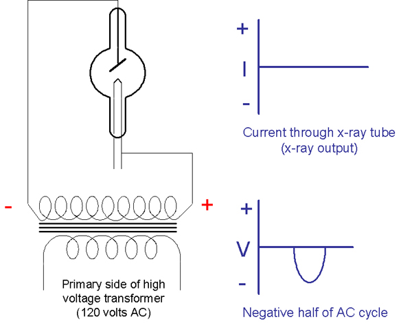
The following diagram shows that the electrons do not flow through a self-rectifying tube during the half of the AC cycle when the anode is negative and the heated cathode is positive. X-rays would not be emitted from the tube.
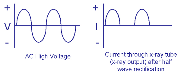
The following diagram shows the potential high voltage across a self-rectifying tube and the current through the tube during two complete cycles. This is half wave rectification.
Some tubes, the "Universal" tube for example, are not self-rectifying. To achieve the half-wave rectification shown above, a circuit employing two valve tubes (or solid state diodes) would be used.
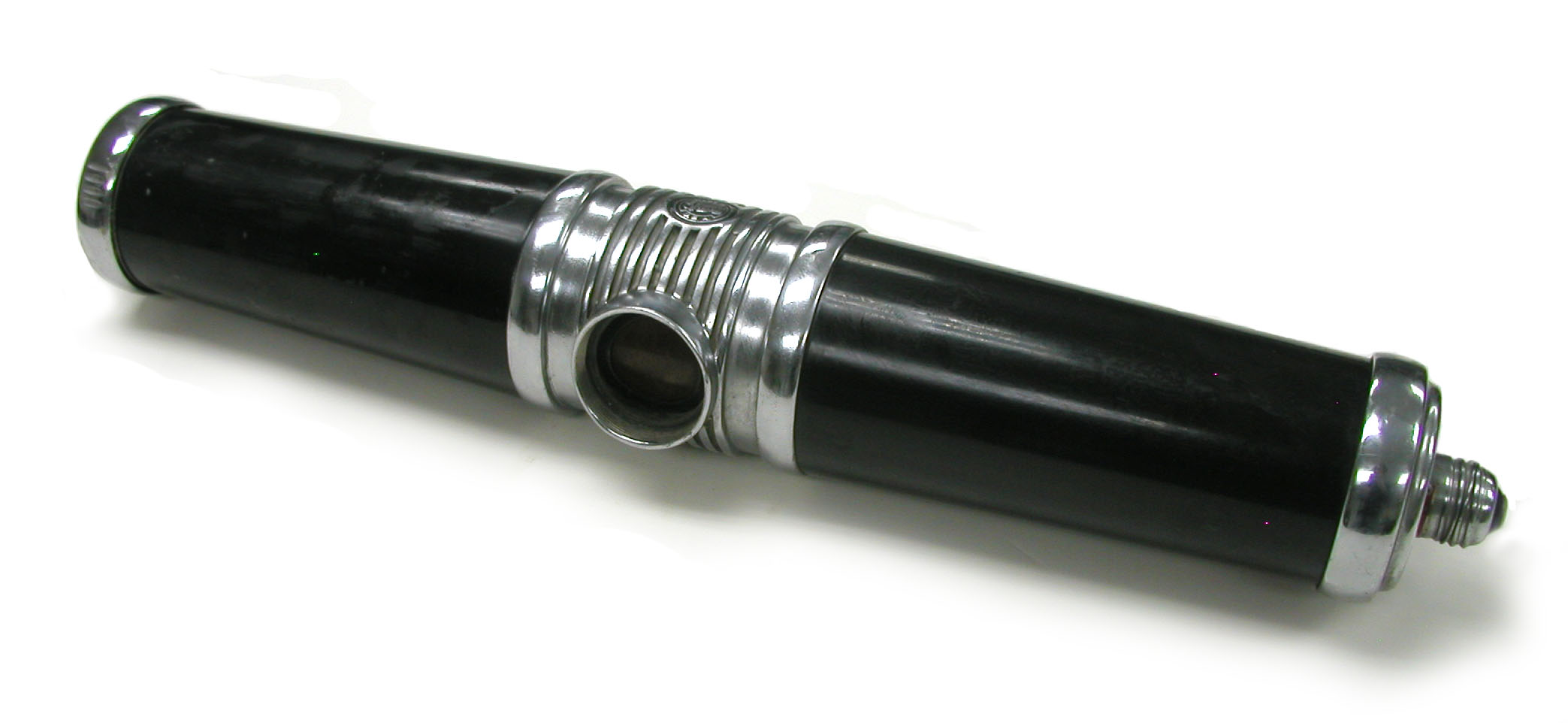
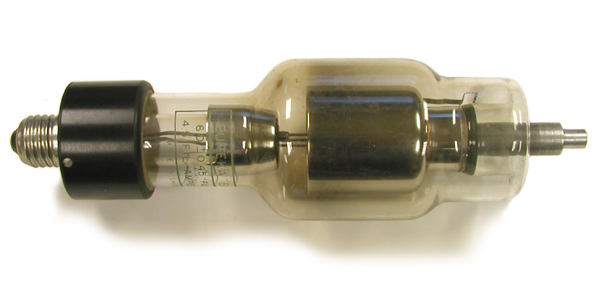
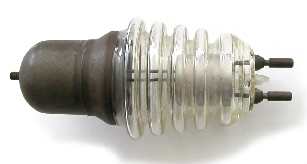
Valve tubes are essentially self-rectifying X-ray tubes that are designed to produce as low an intensity of X-rays as possible. The cathode is a central heated filament that is surrounded by a large annular anode. The electrons from the cathode are not focused and the strike the entire surface area of the anode. Since the latter never gets hot enough to emit electrons, current can only flow in one direction. In other words, it is a one-way valve!
By using a bridge with four valve tubes in it, we can achieve full-wave rectification and double the tube's X-ray output. Such a full wave rectification circuit would work as indicated in the following two diagrams.
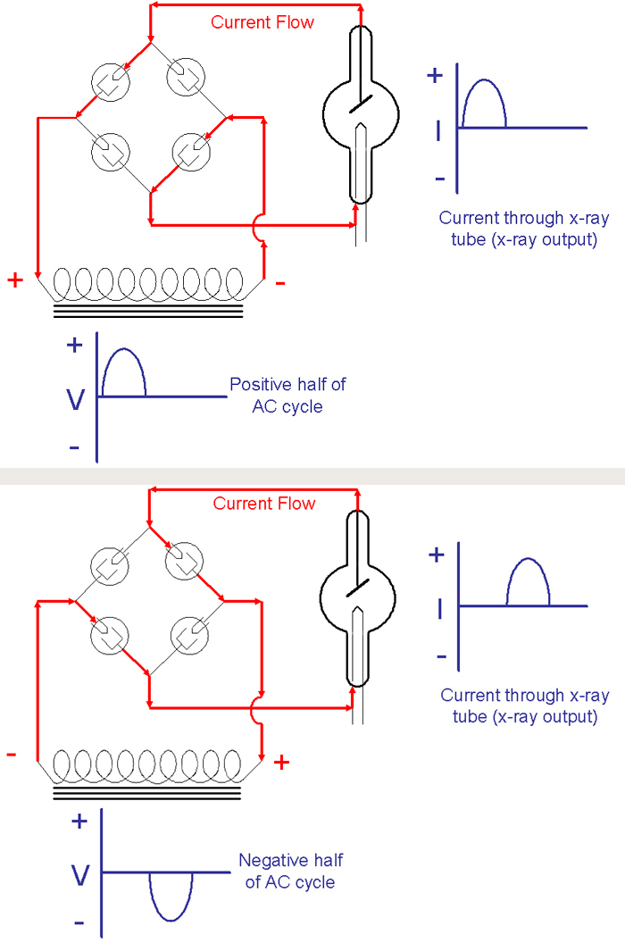
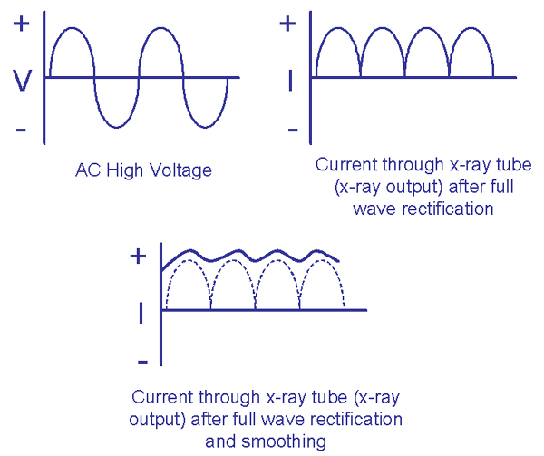
The following diagram shows the potential high voltage across a tube and the current through the tube during two complete cycles when a full wave rectification circuit is employed. It also shows how the range (ripple) of the tube current can be smoothed out by employing a capacitor in the tube circuit. An even smoother current with less ripple can be achieved by employing a three phase system. State of the art systems do even better and produce what is called a constant potential by employing high and medium frequency generators that rectify, smooth, chop and invert the high voltage on the primary side of the high voltage transformer.
-
Eureka EV 3-75T Valve Tube Eureka EV 3-75T Valve Tube
-
General Electric KR-3 Kenotron Tube General Electric KR-3 Kenotron Tube
-
General Electric KR-7/8 Valve Tube General Electric KR-7/8 Valve Tube
-
Kesselring Valve Tube Kesselring Valve Tube
-
Philips Valve Tube - Model 28001/00 Philips Valve Tube - Model 28001/00
-
Tubix Kenotron, the "Valvix" Tubix Kenotron, the "Valvix"